Reworking the MendelFlex

I started testing the MendelFlex again.  I wish I could say it printed fantastic but it didn’t.  I need to do more tuning on it. The bed adhesion was pretty good though.  Since the printer uses 3.00mm filament instead of 1.75mm filament, I have to have 3.00mm filament on hand as well.  The roll of 3.00mm PLA filament that I used before, is really brittle.  It is old and probably needs to spend some time in the filament dehumidifier.  I had some sample translucent red PLA that I pressed into my tests.  The prints that I made were not good.  I opened up a vacuum sealed roll of ABS filament to try out.  Unfortunately I couldn’t get the heated bed temperature to 110°c for the ABS.  When it got around 75°c, the shrill warning beep on the printer went off.  I had to reset the printer.  Using PLA, the heat bed is set to 60°c and the system can handle it. The extra load on the system for temperatures greater than 75°c is too much for the stock Ramps 1.4 controller board.  There are a number of solutions but I am going to try one of the cheaper ones first.  I am going to install an external MOSFET board.  This will take the electrical load off of the controller board.

It did a little bit of rewiring on the system.  I mounted the case for the mosfet board on the printer.

This is what I did for the wiring. I originally had two of the outputs from the PS go to the inputs of the Ramps 1.4 board, one to the 11a side and one to the 5a side. I took the third output from the PS and hooked it up to the external mosfet board on its PS connectors. Correct polarity on all of the outputs. I hooked the heated bed up to the external mosfet board on its heated bed connectors. I hooked up the sensor wires from the external mosfet board to the D8 connector on the Ramps 1.4 board where the heated bed wires were connected.

When the system is powered on there is a red led that lights on the mosfet board. When the Ramps board signals for the heated bed to turn on, a blue led on the mosfet board lights up. The light on the heated bed lights up at the same time showing it is getting power.  The external mosfet got really hot and the the heated bed barely changed temperature.  The alarm sounded on the printer after a short while due to the temperature not rising enough in the set time.  I have a few of those mosfet boards and I tried out another one.  It too didn’t work.  Not sure what’s wrong.

I put a post on the RepRap.org forum thread that was talking about exactly this task which is adding an external mosfet board to the Ramps 1.4 board.

Well on the RepRap.org forum, one senior member said that it looks like my wiring was fine.  There wasn’t any other thing that pointed out what my issue could be.

Maybe I should have shared the PS output that went to the 11A on the Ramps board, with the input on the external mosfet board instead of using that third output.  The output from the PS goes to the external mosfet board and from there to the Ramps board’s 11A inputs.  I tried that alternative wiring and it didn’t work for me either.

Maybe there is something wrong with my Ramps 1.4 board, I don’t know at this point.  I have a Mini Rambo 1.3 controller board that I just installed Marlin 2.1.2.1 on.  It has the settings for MendelFlex.  I can see about swapping the controller boards and testing it out with mosfet board.  Since I am going to probably switch to a 24V setup and this will be good first step in that direction.  My Prusa MK3x has no problem getting the heated bed to 110c using the standard Einsy Rambo 1.2 controller board.  It has a 24V setup.  While I will test the Mini Rambo with the mosfet board, I am not sure I will need to use it when I go to 24V.  But it will be interesting.

The MendelFlex saga continues.


Miayta 310 Build Progress

Recently I spent some time working on the Miyata 310.  I was going to use a 7 speed IRD freewheel sprocket but unfortunately there was some binding between it and the frame.  So I had to use the gold 5 speed New Old Stock (NOS) Suntour freewheel that I had.  It looks good on the rear wheel.  I also added a Suntour chain guard that I picked up.  A lot of people remove them, but I added it for a retro look.

I got a Miyata crankset (made by Sakae) from ebay a while ago and I was going to install it on the bicycle.  But unfortunately when I tried to install it, there was some binding on the frame as well.  Because the mounting bolts for the small chainwheel are too far in, they scrape on the frame as the crank turns.  So I can’t use it.  It does look nice.  I guess I will create a shadow box for those parts that I can’t use.

So I am going to go with the Sugino Mighty crankset that I already had on the frame.  It is a nice crankset.  I believe I mentioned before that Sugino still manufactures cranksets in Japan.  Good quality parts.

Today I did a few things on the build.  I added gear cable guides, cut the stem of the fork to size, put in the seat post, put in the handle bar stem, and put on the derailleurs (both Suntour NOS).  I am using the handle bar stem that I previously had on my Fuji Team.  The seat post is a suspension post that I got in 26.6mm width to fit in the seat tube.  I got a tool from Stein Tool in the US for cutting the 1″ threaded fork tube to size.  Worked great. Used a file on the burs at the end of the cut.


This coming week I will go ahead and finish it up.

Compiling Marlin with Visual Studio Code

Versions 2.0.9.7 and 2.1.2.1 of Marlin support ARM in addition to AVR.  You can use the Arduino IDE or PlatformIO to compile and load the firmware to the device.  I already mentioned the trouble I had with the latest version of the Arduino IDE, so I thought I would look into what PlatformIO was.  Well I was pleasantly surprised to find out that PlatformIO is an extension available for Visual Studio Code (VSCode).  VSCode is like a Swiss army knife when it come to development and I do have it installed.  There are a number of interesting extensions available that are really useful.  IBM has an extension called Z Open Editor that provides tools for IBM Z development along with COBOL, PL/I, HLASM, and REXX language servers.  The old mainframe comes alive and is almost modern in this extension.  Almost. 🙂  But it works really well.

After installing the PlatformIO extension and having already downloaded Marlin versions 2.0.9.7, I went to work on getting it ready for my MendelFlex.  You go through the same process of editing the Configuration.h file with the values that you need for your printer, and then compiling it.  Once you get a clean compile, you can upload the compiled Marlin to your printer.  I used the Configuration.h file that I edited for Marlin 1.1.9.1 as a reference.  While things were similar for the most part, there were a few things that were different.  I was successful in compiling and loading the binary to the MendelFlex, but LCD screen on the printer didn’t refresh itself and displayed blocks.  I wondered for a few minutes on what happened and then I realized that I must have forgotten to set the LCD screen in the Configuration.h file.  Sure enough it was not set and the SD card setting wasn’t set as well.  Set those two items, compiled, and uploaded the Marlin binary up to the printer.  The LCD screen refreshed after the upload and displayed the information I expected.  Success!


Updating Marlin on my MendelFlex

While doing some research on updating the Marlin firmware on my MendelFlex, I came across a few good resources.  First I need to save my current settings by using a program like Pronterface.  Inside of Pronterface I connect to the MendelFlex and then send a M503 command which tells the printer to list its settings.  I then copy and save that information into a file for later use.  Then I edit the Configuration.h file and change certain settings.  I will also be using my old Configuration.h file for reference.  Unfortunately it was not the latest file.  After editing the file I need to open Marlin file in the Arduino Ide.  I downloaded and installed version 2.2.1 of the ide.  While I attempted to load up the Marlin files in the ide, it only got so far and then the ide froze.  In fact my laptop froze and I couldn’t even Ctrl alt delete it!  Tried it again running the ide as Administrator but same thing happened.  I tried down loading the latest nightly version (which is like version 2.2.2) of the Arduino Ide and the same thing happened.  Was looking online to see if anyone else had this issue.  I haven’t found a good solution.

I decided to install an earlier version of the Arduino software.  Version 1.8.19 doesn’t have the Ide moniker tagged to the name.  I was able to verify it worked successfully with Marlin 1.1.9.1.  While it did run, I did have two errors I needed to fix.  After I fixed them, I ran the verification step and got a clean compile.  After I that, I was able run the load process and was successful putting Marlin 1.1.9.1 on to the MendelFlex.

There were a few more things I had to set in the configuration file.  I thought I enabled the SD card reader, but I hadn’t.  I am at a good point now with my settings.  I am expecting a filament dryer this week sometime.  I will need to make sure the 3mm filament I have for the MendelFlex is dry enough to use.  The filament picks up moisture over time and my filament is old.  This can cause trouble with your prints.  When I start printing, then I will make sure I have a good Z offset.  That’s all for now, catch you later.

Lazy Susan in the Workshop

I thought I would create a quick post about the Lazy Susan that I used in my post on my MendelFlex rewiring effort.  You might have noticed it in my Prusa MK3x post too.

I ran across a video on YouTube where they used a Lazy Susan while they were working on the hardware in their computer.  I thought that was a neat idea, so I looked into making a Lazy Susan for similar tasks.  I looked at a number of videos and found some useful information.  Adam Savage had a video where he talks about Lazy Susans and how useful they are.  But the Rockler base plate that he liked was more than I wanted to spend and I didn’t need something as heavy duty.  I looked on Amazon to see what suitable Lazy Susan base plates were available.  I determined that I wanted my Lazy Susan to have a platter of around 21″.  This size would be suitable for use with my largest computer case and also my 3D printers.

Here is the 12″ base that I eventually bought from Amazon.

The Lazy Susan really came in handy while I worked on my Prusa MK3x and on my rewiring effort of the MendelFlex.  It was easy to turn the printers around and work on them.  The MendelFlex is a bit heavy so being able to easily move it was very helpful.  It is a great thing to have in the workshop.  I highly recommend it.

MendelFlex renewal

After I finished with the build of my Prusa MK3x, I turned my attention towards my original 3D printer, the MendelFlex.  I needed to get it back to a working state and also improve its printing ability.  The first thing on the list was to fix the wiring.  It was a mess literally.

Plus I needed to repair the wires to the cooling fan on the printer because one of our cats decided to bite it in half.  They have a bad habit of doing the same thing to wires on earbuds, on USB cables, on ethernet cables, and other things.  We have had to put some plastic conduit around the cables to protect them.  I am going to be doing the same thing while I clean up the wiring.

Initially the ramps controller board on the printer was in a  different location.   It was in the area under the heatbed where the power supply is.  It made it hard to easily access the wiring on the ramps controller board.  So I moved it to the side of the printer.  I also fashioned a better cooling solution by putting a large fan over the ramps board.  The fan was something that I pulled from a power supply.  The fan has led lights that turn on when powered up.  Also the printer initially had a printed extruder carriage, but I replaced it with a metal carriage.  I replaced the bed assembly and heatbed with a bed assembly I had for a P3 Steel printer along with a Prusa Mk42 heatbed.  I added in a BLTouch sensor while doing all of that.  In the process of rewiring the printer I shortened a number of the wire leads.  One reason I kept them long was because I didn’t have crimpers for the connectors needed.

While working on the wiring I also replaced the Prusa MK42 heatbed with a Prusa MK52 heatbet with the removable metal plate.  The removable plate works great on my Prusa MK3x with good adhesion!

The last thing I did was to add a blower fan for print cooling.  I had to fashion a mount for it using parts that I had and a bit of hot glue.  By the way it did work after I finished all the wiring.  Using Pronterface I was able to send a M106 s127 command to the printer to turn it on and set the speed to 50%.  And then an M107 command to stop it.  I made extensive use of zip ties to keep the wiring harnesses in place and out of the way.

Wiring completed!

I did run into one small issue when I was testing out the electronics on the printer.  I was able to engage and move the X, Y, and Z motors from Pronterface.  But when I tried to home the printer, the Y motor didn’t respond for some reason. The X and Z were fine.  After close inspection I found out the the arm on the Y switch stuck into the closed position so the printer thought that Y was where it should be.  After fixing that, the printer was able to home just fine.

The next thing I will be doing is to update Marlin.  Currently I am running 1.1.6.  I will do some research and figure out which version will be best to upgrade to.

Until next time, Happy Printing!

Finally finished building my Prusa MK3x

This build wasn’t a straight up kit so I ran into issues. Here are some of those issues that occurred after building my Prusa MK3x.  From Prusa I had gotten all the steppers, the sensors, and various other parts.  The frame pieces I got from Aliexpress.  The controler board I got from Ultimaker, but it is the one that Prusa also uses. So this is sort of a Frankenstein build.  This build has been in the making for quite a few years.  I should have just gotten a complete kit from Prusa and built that.

Over the years Prusa has upgraded its MK3 printer line with the latest iteration being the MK3S+.  After I finished the build I plugged it in and tried out the calibrations.  While the stepper motors were functioning correctly, things weren’t working.  The filament sensor didn’t seem to work.  The wiring was correct, but it didn’t know if the filament was loaded or not.  The printer kept going through its bed leveling routine before doing a print.  So I had to turn off the filament sensor to continue.  Another issue was that the extruder was not working.  The stepper motor was turning, but no filament was extruding.  The firmware does make you heat up the bed and the hotend before you attempt to do so.  It seemed that filament didn’t go all the way to the hot end for some reason.  So I took apart the hot end and I saw that the PTFE tube in the heatsink was deformed at the opening.  I had another piece so I replaced it.

I reinstalled all the pieces and tried again.  While I was able to insert the filament a little bit more, I still couldn’t extrude any filament.  So I took apart the hotend again.  I looked into the hotend and there was a little bit of plastic blocking the inside of the tube.  The plastic bit had broken off of the retainer clip for the PTFE tube that fit into the heat sink.  Not sure how that happened, but I replaced it.

After I reassembled the extruder, I tried again to extrude some filament and I was successful!

But I needed to check the tension on the gears in the extruder.  There might be too much tension.  I checked the tension on the belts and adjusted them to be with in the stated tolerances.  I used the online app that Prusa had on their website to test the harmonics of the belts after you pluck them.  It seems to work after a fashion.

I did a few test prints and I see that I still need to do some more adjustments to my prints up to par.   One thing is that the bed surface probably should have been cleaned, but I just wanted to see if I could even print.  Remember I said that the filament sensor didn’t see to work, I had to turn off the filament sensor in the settings to even get a print to start.  Part of the printing process the printer does a bed leveling check and goes over like 9 different points on the heatbed taking measurements.  Well after it did the check, it wanted me to unload the filament and then load it back in again.  It went to do the test again.  And after it finished the second time, it again wanted the filament to be unloaded/loaded.  I did that again for a third time before I thought I would turn off the filament sensor in the settings.  After that I was able to start printing.  They weren’t very good prints but it was trying.  But it is a work in progress!  Need to make more adjustments.

My z offset set  apparently is still too high.  So I need to lower it.  After trying a few different Z offsets, I was able to set the Z offset to -0.850mm and get a good first layer.  After that I was able to get a nice print of the Batman logo.

The feeding of the filament just didn’t seem correct also.  I believed that this was throwing things off.  Since the extruder setup I have on the printer is a MK3/MK2.5 type, there were two allen screws that needed to be adjusted.  Looking at the prusa site, it said that the top of the allen screw heads should be flush with the hole the went in.  Previously I had each around 8 full turns in.  I made it flush like the Prusa guide noted.  Then I started over with the first layer test.

I decided to use an IR filament sensor instead of older type I initially installed.  So one last thing I did was to print out a Bondtech IR filament sensor housing adapter that I found online.  Due to the parts I have, the older non IR filament sensor fits my extruder housing, but not the newer IR filament sensor.  While the print turned out great, I had to order a newer IR filament sensor since the rev I had was 1.1 and only rev 1.4 or above works with the firmware.


Until next time.  Happy Printing!

Update on my Miyata 310 Build

It has been a long time since I last made a post.  More than a year.  Much too long.  I pretty much have gathered all the parts I needed for the Miyata 310 build.  In my post talking about bicycle tires, I was trying to see how large of a tire I could use.  While I thought that I had enough clearance to use a 700-38c tire, it turned out to be not the case.  There just wasn’t enough clearance for the rear tire in the frame.  So I went with a 700-35c tire.  Here is a partial frame build with 700-35c tires.  You can see that I have enough clearance with the rear tire.  I will be cutting the top of fork to size later.

Here are pictures showing the front and rear brake clearances.  On the front I am using a Tektro R540 brake and on the rear I am using a Tektro R539 brake.  I had a Tektro R539 on the front, but the brake arm was pressing right on the tire and you couldn’t turn the tire without rubbing it on the brake arm.  Switching to a Tektro R540 on the front gave me plenty of clearance.  The fork that I got for the frame, uses brakes with a  recessed nut.  While the rear brake uses the older nutted style.  I would have tried to use a Tektro R540 for the rear, but it doesn’t come in the old nutted style which the frame needs.

That’s it for now, catch you later.  Bicycle!

Fuji Team Issue Build

At the same time that I got the Miyata 210 frame, I purchased a Fuji Team Issue frame with a front fork.  The frame and fork were carbon fiber and had been listed as being repaired.  Since the seller was a bike shop with a very good rating, I crossed my fingers and hoped it would be ok.  From the pictures nothing seemed to be wrong with it.  And when I received it, everything was fine.  This is the frame that I intend to use as the basis for a bike that I would ride in the neighborhood with my family.  Here is a picture of the frame from the eBay listing and a picture of a complete 2008 model.

This build is a nod to the Fuji Finest that I liked back in the 70s.  This build turned out pretty well.

While I still intend on adding the toe clips and straps that I have on hand, the build is pretty much completed.  I didn’t do a build using original components.  I mixed and matched components that I thought would work well.  One component that I didn’t go with, was standard drop handlebars.  This was due to the negative effect that bending down while gripping them would have on my lower back.  So I opted to use Wald 870 high rise handlebars which would allow me to sit fairly upright.  I paired up some Dia-Compe DC188 brake levers (with matching handle grips) along side the Wald 870 handlebar.  Topping that off that setup with an IRD Power Ratchet Thumb Shifter set.  I included a number of Campagnolo components in the build.  The front and rear brakes are Campagnolo Centaur Dual Pivot Caliper brakes.  The front and rear derailleurs are Campagnolo Racing T derailleurs.  Both of the wheels were built using Campagnolo hubs with Mavic CXP Pro 15mm rims.  The tires are 700-28c Panarace Gravel Kings.  I used Velo Orange Cable sets for the brakes and derailleurs.  The saddle is a Fuji Velo which is on a generic compression seat tube.  The seat tube along with a 90mm Cirrus Cycles Suspension Stem dampens the bumps a bit.  The bottom bracket is an IRD QB-55 (127.5mm x 68mm) with English Threads.  The crankset is a triple from a Fuji S10S (most likely from the 80s).  I used a pair of MKS Sylvan Touring (Black and Silver) pedals.  To finish off the bike I used a kickstand that attached to the bike using the quick release on the rear wheel.  The frame, saddle, and crankset all say Fuji on them.

I will be exclusively riding around the roads in my neighborhood.  I don’t intended to ride the bike on the open roads.  It is too bad the roads in my neighborhood aren’t paved, but it is what it is.

Building a FreeNAS system

I finally decided to build the new NAS system I have been forever talking about.  I have been almost out of space on my ReadyNAS NV+ V2 for a while now. Going to go with FreeNAS and I am using Brian Moses’ 2019 EconoNAS Build as a guide.  My build won’t be quite an EconoNAS build.  I will call it the HexNAS due to the 5 data drives and the 1 cache drive that it will have.

I am using the same ASUS Prime B450M-A/CSM motherboard that he is using.  I am using 2 sticks of 16GB DDR4 Dram instead of the 2 sticks of 4GB DDR4 Dram he used.  So I have a total of 32GB of system memory with two empty memory slots.  I using an old Cooler Master case that was given to me by my friend Paul.  The case is very similar to the Antec NSK4100 case that Brian used.  My cases has 4 external 5.25” bays, 2 external 3.5” bays, and 5 internal 3.5” bays for a total of 11 drive bays.  So it has the same total number of drive bays just like Brian’s case.

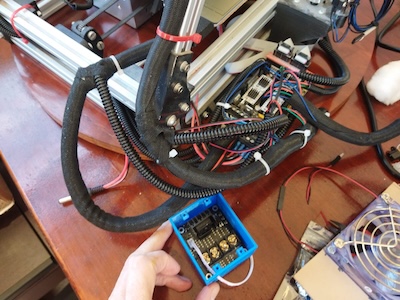
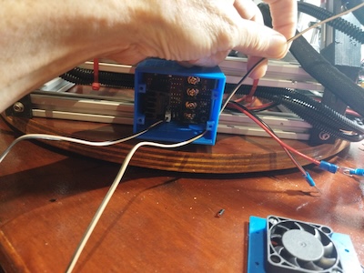
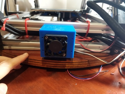
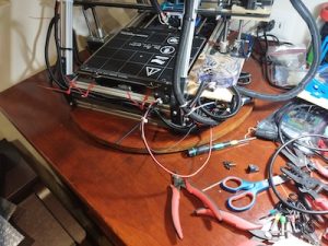
I had to replace the case’s power switch which was missing its leads and was also bad.  The case didn’t have any fans, so I added 5 Noctua fans to it.  Two of the fans were 120mm and three of the fans were 140mm.  These Noctua fans aren’t their premium quiet fans.  But they are still quiet.


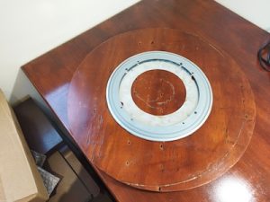
I am going to use a hot swap drive cage that will take up three of the external 5.25” bays and allow me to have five 3.5” drives in the same space.  I was thinking about installing a DVD drive in the fourth 5.25” bay.  But since I have used all of the 6 sata connections on the motherboard, I won’t be able to do that.  Not that I really need a DVD drive.  But if I do, then I can see about adding a card with sata connections.  I also added I/O panel with two USB 3.0 ports, SD card slot, and a USB C port to the case.

For the CPU I used an AMD Ryzen 3 3200G instead of the AMD Ryzen 3 2200G used in the EconoNAS Build.  For the power supply I am using a GameMax 650W 80Plus Bronze unit.  For the OS Drives I am also using SanDisk Ultra Fit Usb 3.1 flash drives, but 32GB instead of 16GB.

I had been thinking about using WD Red 4TB drives, but the newer units use SMR.  So with the issue of SMR rearing its ugly head I couldn’t do that.  Even the new WD 6TB Reds were using SMR.  Really need to use a drive using CMR especially since it seems that FreeNAS does not like SMR drives.

FreeNAS/ZFS does not like the new WD RED SMR drives.

Doing some research on the SMR issue, I found this link that with a list of the WD CMR and SMR drives.  List of WD CMR and SMR hard drives.

Here are some links to the SMR issue that I am talking about.

Surreptitiously Swapping SMR into Hard Drives Must end!

List of know SMR Drives.

I went ahead and bought 5 WD 8TB Red drives for the build.  These drives are CMR.  Brian has a few different hard drive options that he lists, but all of them are using 6 drives.  I am also adding a Crucial BX500 1TB SSD for use as a cache for the zfs pool.  I have those two Ultra Fit 32GB flash drives for the boot drives that I already mentioned.  Once the NAS is built and setup, I will look to sign up with get Blackblaze to add cloud storage/back-up to my NAS.  A NAS isn’t really for backup even though I have been using my ReadyNas NV+ V2 as such.

Here is a link that from Brian’s blog for backing up FreeNAS to Backblaze.  And here is a link to an article that Blackblaze wrote on setting up a FreeNAS cloud storage.  Along a similar vein, here is a link for setting up NextCloud on FreeNAS.

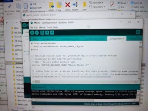
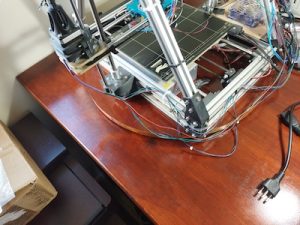
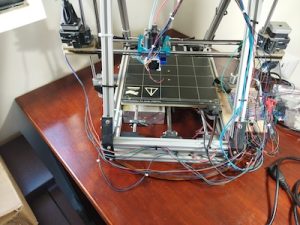
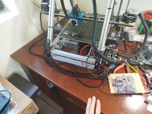
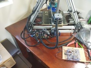
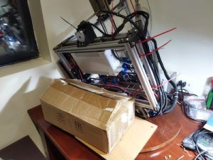
So far I have put together the system without the drives for now.  The system starts ok and goes into the bios.  It is working and I have 32GB of memory! Next I will have to download the latest version of FreeNAS which is currently 11.3-U4.  The FreeNAS iso is 752MB.  Now that I have the iso, I need to burn the iso on to a usb flash drive.  Since I am going to use my Win 10 laptop, I am going to use Rufus to create the bootable FreeNAS install flash drive.  Side note, after I did my install of FreeNAS I came across another install video that used a utility called HashTab that adds an extra tab in the Windows properties menu that will let you see the hash of the file.  A handy utility to have when you want to check if the hash of the file you just downloaded matches what it is suppose to be.  It is free for home use, but if you use it at work, then it is $9.99.

Next I will go to the HexNAS system and bootup the FreeNAS install.  I will be installing FreeNAS on the two SanDisk Ultra Fit Usb 3.1 flash drives.  I will be following one of Brian’s blog post on how to do the install onto the two flash drives.

I booted up the HexNAS with the FreeNAS install flash drive.  I tried to install FreeNAS to the two SanDisk Ultra Fit flash drives, but I kept getting an install error when the process started.  The error was installation failure – gmirror: No such device: swap.  I tried it a number of times more but still kept getting the error each time.  The two SanDisk Ultra Fit flash drives are brand new, so hopefully there is nothing wrong with them.  Did a quick look on line but didn’t really find an answer.  Maybe the flash drives need to be formatted.  What I did was use Rufus to install the FreeNAS install iso on to both of the new flash drives.  Booted up the original FreeNAS install usb drive and tried to install FreeNAS on both of the Ultra Fit flash drives and this time the install worked.  I guess it expected a swap partition to exist on the Ultra Fit flash drives. Not sure though.

While the install was suppose to write FreeNAS onto both of my flash drives, it didn’t seem to do that.  Not sure why, but I used a utility called imageUSB on Windows to save the image from the one bootable FreeNAS system on the flash drive to the my computer.  Then I used imageUSB to copy that image to the second flash drive.  You can also use imageUSB to write an image concurrently to multiple USB Flash Drives.

I successfully booted FreeNAS from that second flash drive.  Then I needed to make sure both devices were in the boot pool. I watched this youtube video and was able to have the boot pool contain both flash drives, so they are mirrored.

The instructions are for 11.2 but they work with 11.3 with a slight difference in the name “Boot Environments” in 11.2 becoming “Boot” in 11.3.  Here are the steps that I followed.  While in the FreeNAS dashboard, click on System to display the items inside of System.  Then click on Boot which will bring up the Boot Environments window.  From there you will Actions menu on the far right and then choose “Boot Pool Status”.  This will bring up the “Boot Pool Status” window.  You will see your default boot pool and if you click on the > next to name of the boot pool, you will se your boot flash drive in the pool.  Mine is /dev/dap0.  On the line that lists your boot flash drive you will need to click on the three dots on the far right of that line and choose “Attach”.  This will allow us to attach our other flash device to the first flash drive.  Select the second flash drive (da1) and check the box for “use all disk space” and press the “Save” button.  It will take a short while for the attach process to finish.  A popup window will let you know that the “Device Attached”.  Close that window.  You will be back in the “Boot Environments” screen.  Click on the “Actions” menu and choose “Boot Pool Status” again.  You will see that the two devices will both be under a “>mirror” selection which completes the task.  If you want to change the default name of the boot pool, you can do that in the “Boot Environments” window.  On the line that has the name of the boot pool, you will click on the three vertical dots on the far right.  This will bring up a menu with a choice to rename.  I renamed my boot pool to freenas-boot.  I need to put a little label on the flash drives so that I can easily identify them in a time of failure.  To identify the drives, it might be best to use at least the first 6 digits of the serial numbers since the numbers at the end aren’t displayed fully.

I have added the data disks and the ssd disk to the machine.  Next I will create the zfs pool.  The zfs options for the VDev are Stripe, Mirroring, Raid-z1, Raid-z2, and Raid-z3. Raid-z1 similar in concept to Raid-5.  But Raid-z1 use is discouraged. Raid-z2 is similar to Raid-6.  It adds a second set of parity data to the VDev.  You can lose two disks while maintaining data integrity.  It requires a minimum of 4 disks.  It is safer than Raid-z1 but has a greater capacity penalty. Raid-z3 adds a third set of parity data to the VDev.  It requires a minimum of 5 disks, but allows you to lose up to 3 disks per VDev.  A hot spare is a drive that isn’t used for storage, but it will instead immediately replace a failed drive. Having a hot spare in the pool will insure that a resilver/rebuild operation will start immediately.  When you are creating your pool, the ADD SPARE button will add a hot spare to your pool.

I am going to go with a Raid-z2 setup which will allow me to lose two disks while maintaining the integrity of the data.  I will be looking into getting Backblaze for my cloud backup.

Logged on to the FreeNAS machine via the web interface so I can create my zfs pool with the 5 drives and the one ssd for the cache.

It is pretty easy to do. Go to Storage->Pools and select the drives for the Data VDev.  I am using Raid-z2 for the Data VDev.  Add the SSD to the Cache VDev. Give the pool a name. Choose to use Encryption or not Zfs Pool.  The GELI encryption can increase security for data stored in a ZFS pool, but it increases pool management complexity.  If you select encryption you must remember to back up the key!  If you lose the key, then you will lose all the data on the disks with no chance of recovery!  I am not going to chose encryption.  Anything that is really important I will encrypt before I put it on the FreeNAS.  I also heard that in the next major FreeNAS version, TrueNAS core, they will likely have new encryption features like per dataset encryption which should make it possible to encrypt data with having to destroy/rebuild the pool.

Update: July 2022, TrueNAS has been out for a while and I did upgrade to it when it came out.  I still haven’t looked into the dataset encryption.  I will put that in another blog post one day.

It didn’t take long to build my pool with the 5 data disks and the 1 cache disk.  Next I will configure users, permissions, and Access Control Lists (ACL) for the users that will access the FreeNAS share that I will be creating.  The first user I will create will be my user.  While creating my user, I will create a group for all the other future users that will be accessing the FreeNAS.  I created the group while adding my user.  In the FreeNAS web interface menu, the path will be Accounts->Users and then click on the Add on the right side.  My username and password will be the same as it is for my Windows 10 laptop.

Now I have to create some shares.  The first thing I need to do is add a few datasets to my ZFS pool.  Go to Storage->Pools on the menu and then on the line that lists your Pool, click on the three dots on the far right to bring up the options for the pool.

I will be adding a dataset to the pool.  I will give the dataset a name, something like Media.  Make sure that the Share Type is SMB since it is going to be a Windows share.  I also will make sure that the Case Sensitivity is Sensitive.  You can add comments if you like.

Once that is done, I will create the actual Share.  Selecting Sharing->Windows Shares (SMB) on the menu will bring up the Samba (SMB) shares list.  Click on the ADD button to add a share.  Set the path to the dataset that you just created.  The dataset will be under your ZFS Pool location.  It will be something like /mnt/ZFSDataPool/Media which ZFSDataPool being the name of your ZFS Pool and Media being a dataset that you created in your pool.  There is a selection box for Use as home share, but I am not going to be selecting that. The selection boxes that are checked will be Enabled and Enable Shadow copies.  What you enter for the name of the Share will be what you will see when you access from your Windows computer.  The Share name can be different from the dataset name that it is attached to.  You will want to make sure that the SMB service has started and will automatically start when the system boot up.  You will be prompted to do so.  But you can go to Services on the menu and start up the service and also check the Start Automatically box for the Service.

After you have create the SMB share, you will want to edit the ACL for the share you just created.  On the SMB share list, you want to put your cursor on the line for the share you just created.  Then click on the three dots on the right to bring up the options for the share and select Edit ACL.

Here in the Edit ACL window, you will be adding an ACL Item.  You can add a group or user.  If you have a a lot of users assigned to a group, then your probably would want to add that group.  Or you can just add individual users. You will need at least one of the ACL Items to have the Inherit flag set.

Then I should be able to access the shares from my Windows laptop.  And I was.  Since I have a Apple Mac, I also created an AFP share and attached it to those datasets that I added SMB share too.  I was able to access the Shares on the FreeNAS from my Mac too.

There are other things you can do later like work with Virtual Machines and Jails.

If I get a chance I am going to look into some free FreeNAS/TrueNAS training at ixSystems .

That’s it for now.