Rambo and the MendelFlex

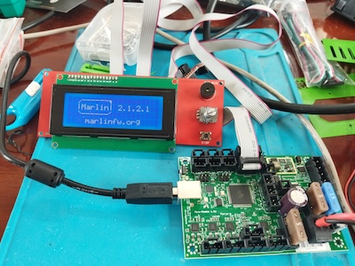
This is a continuation of the effort to use an external mosfet board with the MendelFlex.  I had been able to install Marlin 2.1.2.1 on the Mini Rambo 1.3 while trying a few things that I gathered from my researching on the internet.

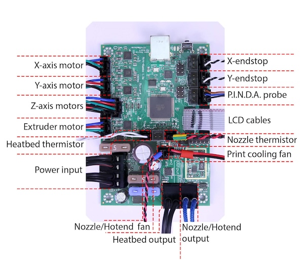
Here is a picture of the connections on the Mini Rambo.  A good source for 3D printer information is reprap.org and this is where I got this picture from.  The link of the page is  reprap.org/wiki/Rambo.

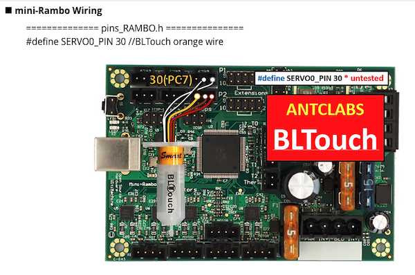
While the picture above show the use of a PINDA probe, the MendelFlex is using a BLTouch probe.  Here is how it should be connected.

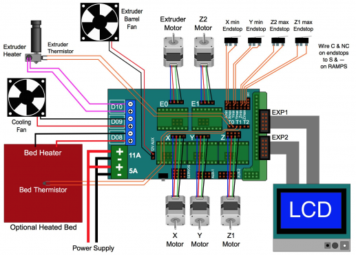
For reference here is a picture of the connections on the Ramps 1.4 controller

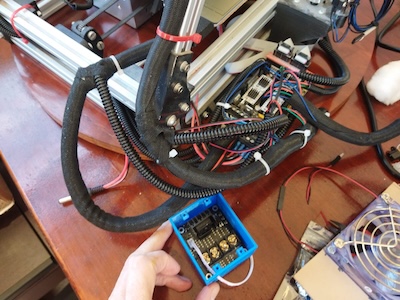
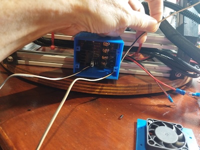
Now it’s time to start the swapping out of the controller boards.

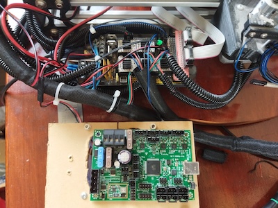
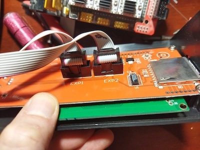
After I finished changing the controller, I installed all the wiring while making sure the connections were correct.  I added power to the Mini Rambo and turned it on.  The LCD did not turn on and show the boot up sequence.  I disconnecting all the connectors while leaving the power and the LCD screen connected.  Still nothing happened.  I removed the Mini Rambo and took it over to the test area.  I had an LCD screen there which I had previously used with success on the Mini Rambo.  I plugged in the LCD screen, turned on the power and the LCD showed the boot up sequence.  I went back to the MendelFlex and I connected the Ramps 1.4 board to the LCD screen.  After I connected the power, I turned the MendelFlex on, and the LCD screen displayed the boot up sequence.  As this point I removed the LCD case from the MendelFlex and looked at the LCD board.  After looking at board, I knew what the problem was.  It was a matter of poor quality control.  The connectors were installed backwards.  It had been such a long time that I forgot about the backwards connectors on the LCD setup on the MendelFlex.

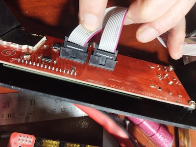
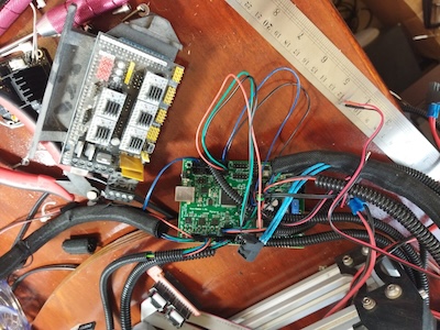
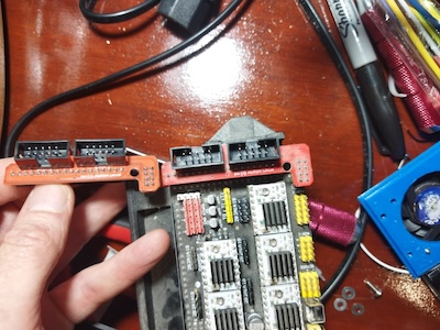
The ribbon cable connectors on the LCD adapter card that the Ramps 1.4 used, were backwards as well.  So the two backwards connector sets worked with each other, but not any correctly installed connectors.  In this picture, the adapter board on the left has the connectors installed correctly, while the adapter board on the right does not.

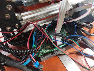
I went ahead and cut some plastic off both of the connectors of the LCD screen so I could plug in the ribbon cables to the correct pins.

After that I turned on the MendelFlex and the LCD finally showed the boot up sequence.

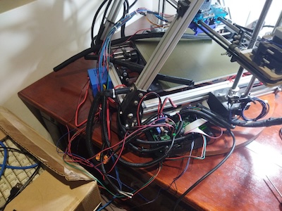
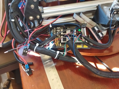
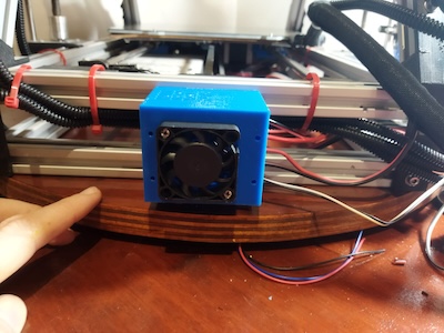
I went ahead and hooked up the wiring. I did a few movement tests.  I moved the X axis, Y axis, and Z axis successfully.  When I continue I will do further testing.

Reworking the MendelFlex

I started testing the MendelFlex again.  I wish I could say it printed fantastic but it didn’t.  I need to do more tuning on it. The bed adhesion was pretty good though.  Since the printer uses 3.00mm filament instead of 1.75mm filament, I have to have 3.00mm filament on hand as well.  The roll of 3.00mm PLA filament that I used before, is really brittle.  It is old and probably needs to spend some time in the filament dehumidifier.  I had some sample translucent red PLA that I pressed into my tests.  The prints that I made were not good.  I opened up a vacuum sealed roll of ABS filament to try out.  Unfortunately I couldn’t get the heated bed temperature to 110°c for the ABS.  When it got around 75°c, the shrill warning beep on the printer went off.  I had to reset the printer.  Using PLA, the heat bed is set to 60°c and the system can handle it. The extra load on the system for temperatures greater than 75°c is too much for the stock Ramps 1.4 controller board.  There are a number of solutions but I am going to try one of the cheaper ones first.  I am going to install an external MOSFET board.  This will take the electrical load off of the controller board.

It did a little bit of rewiring on the system.  I mounted the case for the mosfet board on the printer.

This is what I did for the wiring. I originally had two of the outputs from the PS go to the inputs of the Ramps 1.4 board, one to the 11a side and one to the 5a side. I took the third output from the PS and hooked it up to the external mosfet board on its PS connectors. Correct polarity on all of the outputs. I hooked the heated bed up to the external mosfet board on its heated bed connectors. I hooked up the sensor wires from the external mosfet board to the D8 connector on the Ramps 1.4 board where the heated bed wires were connected.

When the system is powered on there is a red led that lights on the mosfet board. When the Ramps board signals for the heated bed to turn on, a blue led on the mosfet board lights up. The light on the heated bed lights up at the same time showing it is getting power.  The external mosfet got really hot and the the heated bed barely changed temperature.  The alarm sounded on the printer after a short while due to the temperature not rising enough in the set time.  I have a few of those mosfet boards and I tried out another one.  It too didn’t work.  Not sure what’s wrong.

I put a post on the RepRap.org forum thread that was talking about exactly this task which is adding an external mosfet board to the Ramps 1.4 board.

Well on the RepRap.org forum, one senior member said that it looks like my wiring was fine.  There wasn’t any other thing that pointed out what my issue could be.

Maybe I should have shared the PS output that went to the 11A on the Ramps board, with the input on the external mosfet board instead of using that third output.  The output from the PS goes to the external mosfet board and from there to the Ramps board’s 11A inputs.  I tried that alternative wiring and it didn’t work for me either.

Maybe there is something wrong with my Ramps 1.4 board, I don’t know at this point.  I have a Mini Rambo 1.3 controller board that I just installed Marlin 2.1.2.1 on.  It has the settings for MendelFlex.  I can see about swapping the controller boards and testing it out with mosfet board.  Since I am going to probably switch to a 24V setup and this will be good first step in that direction.  My Prusa MK3x has no problem getting the heated bed to 110c using the standard Einsy Rambo 1.2 controller board.  It has a 24V setup.  While I will test the Mini Rambo with the mosfet board, I am not sure I will need to use it when I go to 24V.  But it will be interesting.

The MendelFlex saga continues.