Soldering Temperatures

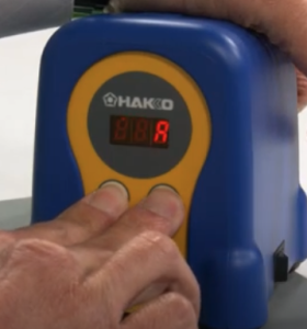
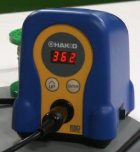
What’s the correct temperature to set your soldering station to?  I am trying to figure out what temperature presets should I use on my Hakko FX-888D.  I can have up to 5 presets.

According to Collin’s Lab Notes, the short answer is for leaded solder to set your iron to 650°F/350°C.  And for lead-free solder to set your iron to 750°F/400°C.  The long answer is that it depends on two different variables, tip size and joint size.  A larger tip is better at transferring heat, so you can use lower temperatures.  A smaller tip transfers less heat so you need more heat.  On the other side of the equation, a larger joint needs more heat so a higher temperature setting is desirable.  A smaller joint heats up faster and it needs less heat, so a lower temperature setting should be used.  Keep in mind that higher temperatures affect the life of your soldering iron tips.  So when in doubt, use a lower temperature and increase the temperature when needed.

The HAKKO Knowldege Base also provided good information on the different optimal soldering temperatures for leaded solder and lead-free solder.  While I am providing the information for the link, I am going to present the information here from the knowledge base.  But in a nutshell, the optimal temperature setting should be high enough to achieve a soldering connection at 50°C above the melting point of the solder, while also adding in more heat (70°C to 100°C) for a heat reserve for quick thermal recovery of the tip after a connection is made.  This recovery range factors in the performance of the soldering station and type of solder used.  Here is a chart for reference on the melting points of various solders.

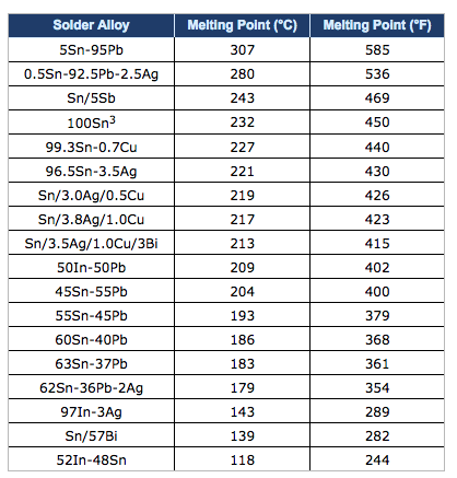
As a general rule of thumb, the optimal soldering temperature should be high enough so that when making a solder connection, the solder is approximately 50°C above its melting point.  The set temperature for a soldering station should be an additional 70°C to 100°C higher to provide a heat reserve for the quick thermal recovery of the tip after the solder connection is made.  The performance of the soldering station used and the type of solder used will determine the optimal soldering temperature.

For example, lets look at the melting points of common solders:

  • Tin/Lead (Sn63/Pb37) – 183°C
  • SAC 305 (Sn/Ag3.0/Cu0.5) – 220°C
  • SN100 (Sn) – 232°C

Now let’s add the 50°C we need for making a good soldering connection:

  • Tin/Lead: 183°C + 50°C = 233°C
  • SAC 305: 220°C + 50°C = 270°C
  • SN100: 232°C + 50°C = 282°C

We now need to consider the type of soldering station we are using.  If we are using a Hakko 936 Soldering Station which has very good performance, we should add approximately 100°C as the heat reserve for quick thermal recovery.  The resulting temperature settings are:

  • Tin/Lead: 233°C + 100°C = 333°C
  • SAC 305: 270°C + 100°C = 370°C
  • SN100:  282°C + 100°C = 382°C

As you can see, switching from tin/lead solder to lead-free solder requires a higher optimal temperature setting.  But before you raise your set temperature, you must consider the setting you are currently using, and the performance of the soldering station.  Most Hakko soldering stations are typically set at about 399°C (750°F).  Considering that, the optimal temperature setting does not need to be adjusted when changing from tin/lead solder to lead free solder.

Now let’s look at the optimal temperature settings if we were using a high performace soldering station such as the Hakko FX-951 Soldering Station.  Because of the performance of this soldering station and the thermal recovery performance of the composite tips, we only need to add 70°C as the heat reserve for quick thermal recovery.  The resulting temperature settings are:

  • Tin/Lead: 233°C + 70°C = 303°C
  • SAC 305: 270°C + 70°C = 340°C
  • SN100: 282°C + 70°C = 352°C

Again, considering that most Hakko soldering stations are typically set at about 399°C (750°F), we do not need to raise the set temperature.  In fact, we can use a lower set temperature which will help extend the service life of the soldering iron tip and reduces the risk of damage to the PCB and components.

That wraps up this post.

Hakko FX-888D Setup

Recently i noticed that Hakko has released a new version of their FX-888D soldering station.  The new model is the FX-888DX.  The main difference I can see is the addition of single adjustment knob which replaces the two adjustments buttons that the FX-888D had.

The new model can also use an optional 95w iron for more demanding soldering work.

I have the FX-888D and it is good soldering station.  It is 65w and has a temperature range of 120°F to 899°F (50°C to 480°C).  The time to reach 660°F (349°C) is 26 seconds.  A good soldering station.

I will go through the setup of the FX-888D in order to document the process.  There are a four parameters that you can change in the setup .  You can choose either Celsius or Fahrenheit as the display temperature.  You can set a base temperature so that an alarm will sound if the station doesn’t go pass this value.  You can choose between normal mode or preset mode.  Preset will allow you to set a number of different temperature presets.  And the last thing is setting a password.  This probably could be useful to people.

In order to get into the parameter settings, press and hold the UP button while turning on the FX-888D.  Let the button go when the display lights up.  Next 01 will flash to indicate that you at Preset 01.  Press the Enter button to allow you to set the display temperature scale to either Celsius (C) or Fahrenheit (F).   Pressing the UP button will cycle through C and F.  By pressing the Enter button, you will set your chosen temperature scale.  The 01 will be flashing again.  Press the UP button to go to the next Parameter which is 03.

Parameter 03 is to set a base temperature so that an alarm will sound if the station doesn’t go pass this base value after a certain time.  We can press the Enter button to go into this mode to set the desired value.  Using the UP button and the Enter button will allow us cycle through the digits to set the desired value. Pressing the UP button at the flashing parameter number takes us to the next parameter.

Parameter 11 is next and it allows us to choose between normal mode or preset mode.  Normal mode is 0 and preset is 1.  Normal mode just has one preset temperature wile Preset mode will allow you to set a number of different temperature presets, up to 5.  We don’t each preset temperature value here, we just set the number of presets.

Parameter 14 is next and it is about setting a password.  This probably could be useful, but I am not going to use it and not going to describe it here.

When we are done changing the parameters that we want, we press and hold the Enter button for a second.  A Y will flash on the display.  If we want to save the values, we will press enter again.  If we hadn’t wanted to save the values, when the Y was flashing, we would have pressed the UP button to cycle through to a flashing N.  Then we would have pressed the Enter button to not save the changes.

How to change your set or preset temperatures.  For example if the default set value was 750 and you wanted to set it to 660.  First press and hold the Enter button.  The hundreds digit on the display will begin to flash.  You will use to UP button to cycle through to the digit value you want.   In our example the 7 is flashing and I would press the UP button, scrolling through until the 6 is displaying.  Press the Enter button to move over to the tens digit.  Press the UP button to scroll through to the desired value.  Press the Enter button to move over to the ones digit.  Make a change to this value if needed by using the UP button.  Then press the Enter button to finish.

This will work for if you have a number of presets.  For the presets you will use the UP button to select the various presets, P1, P2, etc. up to P5 if you have 5.  Press the Enter button to set the iron temperature to the preset that you have chosen.  When it heats up to its value, you can do the change as described prior.

From time to time you probably want to dial in or adjust the set temperature on your FX-888D, so that it will be more accurate.  You will need a way to measure the temperature of your tip.  There are tip temperature measurement tools.  Hakko has the SG-100B.  With the iron on and it is at its set temperature, measure the tip temperature with the tool.  Once you do that, you will press and hold the UP button on the FX-888D to get into adjustment mode.  Then you set the value to the temperature that you measured with the tip temperature measurement tool.  The UP button will cycle through the digits.  The Enter button will take you to the next digit and will also exit when you are at the 1s digit.

If for some reason, you made mistakes when you made your changes, you might want to do a factory reset. Here is how to do a factory reset on your FX-888D.  When the power is off, press and hold both the UP and Enter buttons.  Turn on the power.  When the power comes on your will get a flashing A which means Asia.

Press the UP button one time to get a flashing U which means US.  Press the Enter button to choose this selection.  The FX-888D has been reset to its factory settings.

Here are the video links where I got my information from.  There is no guarantee that any video that I link to will be available later, so I tried my best to document the information.

FX-888D Setting and Adjustments document.

Here is a very short video by Hakko on the parameter settings on your Hakko FX-888D.

Here is another video where we are shown how to set the different parameters.

Here is the video by Hakko where I got the information on changing vs adjusting the soldering temperature.

Here is a video by Hakko on setting the Preset Temperatures.

Here is a short video by Hakko on setting the Temperature on your FX-888D.

Here is a short video by Hakko on using the Adjust mode.

How To Set and Use the Password Lockout Feature on your FX-888D.

My 3D Printing Journey

My 3D printing journey has been a long one.  I am certainly no expert, but I have learned a lot.  A lot of the info is from my favorite Youtube 3D printing channels while the reset has been on various forums and internet searches.

My first 3D printer was the MendelFlex, which I have talked about in this blog.  I had some success with it, but ultimately I dismantled it for parts.  My second 3D printer was a P3Steel.  I got the 3mm steel frame cut using the design files from the Thingiverse P3Stee design named the “Leonardo” .  I modified the original DXF files and added a mount for the 2004 LCD display which came from another P3Steel design.  The build turned out pretty well.  I am in the process of getting it working.  I need to finish calibrating the axis steps.  The setting of 1900 I had for the E step was much too high.  It caused the extruder to click while I was testing the filament feeding.  I set it to 575 and the clicking stopped.  But I will have to fine tune it.  Here are the youtube videos that describe the tuning process.  It is in two parts.  Here is part 1 and here is part 2.

My third 3D printer is my Prusa Mk3x.  Since most of the parts originally came from Prusa sans the frame pieces, have designated it to be Mk3x.  In the firmware it is a Mk3S.  I added modifications to the X axis and Y axis by adding Hiwin linear rails to the printer.  I also added an E3D Revo V6 hotend to facilitate easy nozzle changes.  This modification will eliminate any chance of filament leaking in the heatblock since the nozzle and the throat tube are one piece on the Revo.  I have been getting pretty decent prints.  Not perfect but I have remember to dial in the settings for each filament.  I am printing parts for other printers.  Replication sort of. 🙂

Miyata 310 Completion

I had said that I was going to finish up the Miyata 310 build a few weeks back, but that week turned out to be really hot.  And the next week as well.  So I started working again on the build a few days ago.  I installed the handle bars, the shifters, the brake handles, and started to size the housing for brake cables and shifter cables.

Today I finished cutting the cable housings to size.  Installed the brake and derailleur cables.  Here I am testing the movement of the derailleurs.

Now I am sizing and installing the chain.  I get to use my new Hozan chain tool.  There are three popular ways to size your new chain.  The first method was used by the late Sheldon Brown who was a well known bicycle mechanic and proponent of bicycling.  His website had tons of information on bicycles which I have used on a number of occasions.  His website is still maintained by his friends and family  To use the Sheldon Brown chain sizing method, you put the chain around the larges sprocket on your rear gears and then put the chain around the largest chainwheel on the front. Usually the front derailleur is shifted to the largest chainwheel, but I don’t see that it matters.  Don’t feed the chain through the rear derailleur, just make sure the derailleur is out of your way by shifting it to the smallest sprocket.  But make sure the chain fits on every tooth of the rear large sprocket that it can be on.  As the chain is around the rear large sprocket and the front largest chainwheel, pull the chain tight and find the closest matching link that you can connect to.  Then go back down the chain one link (maybe 2 if you are using a master link)  and at that point is where you will break the chain to size it.

The second chain sizing method needs the bicycle to be on flat and level ground.  You will feed the chain (which has the end that with accept the pin) around the smallest chainwheel on the front.  Next feed the other end of the chain around the smallest sprocket on the rear and also around and through the rear derailleur pickup wheels.  The chain end from the front will overlap the rear end of the chain.  Pull the chain ends gently together until the point where the cage of the rear derailleur moves forward.  At this point the chain coming off the rear derailleur ideally should have enough clearance not to rub against the top guide pulley on the derailleur.  Basically there should be a minimum of 1/2″ or 15mm gap.  On the overlap, you will break the chain at the point where the proper ends meet.  Note that if you are using a power link, then you have to go one link farther.

The third chain sizing method uses mathematics to calculate the chain length.  First you need to find out how many teeth your biggest sprocket on the rear  has and then find out how many teeth your biggest chainwheel on the front has.  Then measure the length of your chain stay which will be from the center of your rear wheel to the center of your chainset.  Measure it to the closest .125″ (1/8″).   I am going to do a calculation using the numbers I gathered from my Miyata which has a 53 tooth front chainring, a 34 tooth large rear sprocket, and a length of 16.25″ for the chainstay.  So the equation will be this for the Miyata:

(16.25 x 2) + (53 / 4) + (34 / 4) + 1

32.5 + 13.25 + 8.5 + 1 = 55.25″

This last method is especially helpful if you change you rear sprocket/cassette or your front chainwheel.  I was familiar with the first two methods, but not this third method.  I used the second method when I sized up the new chain for my Fuji build.  This time I am going to use the Sheldon Brown sizing method.  After I size the chain, I will compare the length that I come up with to the Math sizing method and see how close they are.

In the picture I made a mistake marking the link, I need to go over to the start of the next link.  So instead of 55″ it was almost 55.5″.  So 55″ and 55.5″ were still in the ballpark and very close to the measurement of 55.25″ that I calculated.

I was able to install the chain but had a little bit of trouble with the pin for the Shimano chain.  You are supposed to install a chain with the side that has writing on it facing the outside.  But this Shimano chain had writing on both sides, so I am not sure which side is suppose to face out in this case.

After I installed the chain I adjusted the high/low setting for the derailleurs.  Then I took the Miyata on a few test rides.  I moved the saddle back twice, a little bit after each of two short rides in the neighborhood.

I completed about 99% of the build.  I need to install the toe clips and a speedometer I got for it.  But I will mark the build as completed!


Hozan Bicycle Tools

I don’t remember when I first became aware of Hozan Tools, but they have been around since 1946.  Besides making bicycle tools, they make tools for the electronics industry.

I have a number of their tools on my wish list.  The first one is the C-702 Spoke Threading Machine.  It is for use with round spokes.  There are 3 different cutting head sizes available (13, 14, and 15) depending on your spoke thickness.  You can cut a long spoke to the size you need and then use the C-702 to put threads on the spoke by turning the crank arm to do so.   It actually cold rolls the tread on to a spoke.  It comes in handy for those people who build a lot of bicycle wheels.  I have yet to build my first wheel, but that is one of the things I want to do.  You can get it on Amazon with one cutting head for around $119 USD which is cheaper than I have seen it on eBay.  Also on Amazon I have seen a cutting head is around $72 USD which is the cheapest I have found.

I saw a Hozan C-701 Spoke Threading Machine on eBay a while back.  It is motor driven.  I only saw that one unit there and someone snatched it up.  I saw a few videos of it in action and it was very easy to use.  It was around $450 USD on eBay which is a lot more expensive that you can get a C-702 on Amazon.  But I saw that a brand new unit with a #13 head at Modern Bike was $1500 USD but with free shipping!

The Hozan C-701 is not the most expensive Spoke Threading Machine I’ve seen online.  Wheel Fanatyk has a Morizumi that will cut and thread the spoke like you can get from the factory.  But it comes in at a whopping $3800 USD!  It is manual action where you pull a lever down and cut the spoke.  You then put the spoke into the threading area where you pull a lever down and push it back up for a finished spoke.  Really fast if you are producing a lot of spokes.  Not sure how many spokes you need to run through the machine before you get a return for your money.


Actually I forgot about the Phil Wood spoke machine which is an astronomical $7050 USD!  Not even going to show a picture for that thing.  I wonder how much the Phil Wood name adds to the price.

I got off the subject of the post, namely Hozan tools.  I have a number of cheap bicycle chain tools.  I have one that is part of a BikeHand tool set, and a few others that I picked up from various places.  All of them work but they are basically junk.  Which brings me to my latest chain tool, the Hozan C-371.

The C-371 is a heavy duty chain tool it dwarfs the other chain tools.  It is prescision made.  And at $74 USD it better be.

The BikeHand chain tool broke while I was using it a while back.  The metal piece that the chain fit over broke right off.  The metal isn’t very strong.


The handle of the C-371 holds a spare chain link press pin.

I am going to be using this tool when I install the chain on my Miyata 310 this week.


Lazy Susan in the Workshop

I thought I would create a quick post about the Lazy Susan that I used in my post on my MendelFlex rewiring effort.  You might have noticed it in my Prusa MK3x post too.

I ran across a video on YouTube where they used a Lazy Susan while they were working on the hardware in their computer.  I thought that was a neat idea, so I looked into making a Lazy Susan for similar tasks.  I looked at a number of videos and found some useful information.  Adam Savage had a video where he talks about Lazy Susans and how useful they are.  But the Rockler base plate that he liked was more than I wanted to spend and I didn’t need something as heavy duty.  I looked on Amazon to see what suitable Lazy Susan base plates were available.  I determined that I wanted my Lazy Susan to have a platter of around 21″.  This size would be suitable for use with my largest computer case and also my 3D printers.

Here is the 12″ base that I eventually bought from Amazon.

The Lazy Susan really came in handy while I worked on my Prusa MK3x and on my rewiring effort of the MendelFlex.  It was easy to turn the printers around and work on them.  The MendelFlex is a bit heavy so being able to easily move it was very helpful.  It is a great thing to have in the workshop.  I highly recommend it.