It’s Alive!

Yes, it has been quite a while since my last post.  This blog started out on my friend’s server, but he shutdown the server last summer and gave me a backup of my blog.  Just today I created a subdomain for my WordPress blog.   My friend used the plugin All-in-One WP Migration to backup my blog.  I installed the same plugin and restored the backup file onto my subdomain.  There were a few minor issues about the restore, but only one in particular is worth mentioning.  The restore overwrote the WP database and I forgot what the passwords were for the admin and editor accounts in the backup.  I had to go into phpMyAdmin on cPanel to browse the WP database.  From there I looked at the user table.  The passwords for the accounts are in an MD5 hash.  So I can’t just type in a new password.  I need to generate an MD5 hash of the new password that I want to use.  This website has an MD5 hash generator which I was able to use.

http://www.passwordtool.hu/md5-password-hash-generator

Once I generated an MD5 hash, I used it to update the password field (user_pass) for the admin account and my editor account in the users table.  That update allowed me to logon to my WP admin account and create this post.


Changing to the BLTouch

Unfortunately the Pinda Probe experiment did not work out as I had hoped it would.  The MK42 bed was really made to be used with the Prusa Pinda Probe  in a MK2s.  Meaning the offsets from the hotend and the Pinda Probe needed to match what Prusa is using.  That is because the MK42 has nine probe points that the Pinda Probe will detect correctly when it is over them.  Other areas on the MK42 bed don’t trigger the probe.

So I removed the Pinda Probe and installed a BLTouch probe.  This is the new Smart version of the BLTouch.  It took me a while to install it.  I used an adjustable mount for a BLTouch that I got from Thingiverse.com.  The mount was for a different printer, but I was able to use it with a little tweaking of the mounting holes.  I used one of Thingiverse’s printer services (Treatstock) to have the mount printed for me.  I would have liked to have had the BLTouch mounted closer to the hotend, but due to the design of the carriage I was not able to.  It is about 52mm away from the hotend now.  The minimal distance is 15mm.  The mount was for made for another printer after all.  Maybe in the future I can do something about that and get it a bit closer.  Probable will have to design a new mount.

I made more changes to the Configuration.h file for my Marlin setup.  Since I was already familiar with what I had to do, it didn’t take terribly long.  I was able to set up the bed leveling using the BLTouch.  The printer probes the bed with the BLTouch.  Next step will be to try to print something.


I did make another minor change to the printer.  I changed the LCD mount.  This mount blends in more than the other one did.  Note that the picture with the first lcd mount was taken before I made a lot of the prior changes.

Adding the Pinda Probe

This post is about adding a Pinda probe to the 3D printer.  In order to do that I needed to make a probe mount first.  I thought about designing a mount in Sketchup and printing it. But that meant I had to learn how to use Sketchup and I would have to print the design too.   While I do have a pretty good book on Sketchup, the problem of printing the mount with the printer as it currently works, ruled out that idea.  So I looked to see if I could fashion a mount out of stuff I had on hand.

I found a thin stainless steel metal piece.  I believe it was a cover for some computer component, I’ve forgotten exactly what.  Here it is after cutting it, bending it in places, and drilling a few holes.

Next I put the Pinda probe in the mount.

Here I have the Pinda probe mounted on the printer.

One thing I had to do in order to configure the probe settings, was to measure the offset from the printhead to the probe.  It was -25mm on the X axis and -5.5mm on the Y axis.  I will plug these numbers into the Configuration.h file for my Marlin code.  There are a number of other settings I have to change, but for now I will end this post and report on those changes later in another post.

Getting on the right track

With Thanksgiving at the end of November and Christmas time upon us, I haven’t had time to give an update.  So it has been a while since I last posted an entry,  so I thought I should give a quick update.  I still don’t have things sorted out completely with the 3D printer, but I am getting closer.  I was able to print a few calibration items.

I printed a calibration cube, but it was a bit too tall.  So I had to calibrate the Z axis again.  My next try was pretty much close to what it should have been.  Here is a picture of the two prints.  On the left is the second try.

There are still some major issues that need to be fixed, like having the filament at times form a blob of string around the hot end.  Oh well, I will solve that in time.

Out with the old and in with the new

The OVM20 I ordered from Tindie finally arrived.  Time to replace the old electronic setup with the new board.

With all the wires it is hard to tell that there is more space there.  After wiring up the OVM20, it took some time to upload the sketch to it.  The OVM20 uses a micro USB connector, so I had to find a cable to use.  I downloaded the latest version of the Arduino IDE plus the latest Marlin firmware.  I made my changes to the Configuration.h file and then compiled the Marlin firmware.  Once I got a clean compile, I uploaded the firmware to the OVM20.

While running the homing test with printrun, I noticed that the z motors were going in the wrong direction.  They were going up instead of going down.  I had the z motors plugged in the same direction that I had plugged in the x, y, and extruder motors on the original electronic setup.  I unplugged the z connectors and reversed them.  That fixed the direction issue.  Next I did the movement test where I move x, y, and z to 100.  Then I measure how much they moved.  When I previously did the movement tests on the old electronics, the x and y were correct, but the z was not.  This time all the axis movements were off.  Each was only moving half of what they should.  I made adjustments in the Marlin setup and uploaded the changes to the OVM20.  That issue was fixed.  I did a preliminary test on the heat bed.  I let the heat bed get to 75C and then I shut it off.  I didn’t time how long it took.  I quit for the night since it was getting late.  I still have to adjust the stepper motors since they are humming a bit with the default settings of the OVM20.  I will also do timed heat tests on the hot end and the heat bed.  Until next time.

Making tweaks to the 3d Printer

Today I took the opportunity to change out the carriage for the hot end assembly.  In my parts bin I had a blue metal carriage that I had gotten from RepRapWorld.  The metal carriage holds the four bearings firmly and the bearings are aligned properly.  The existing printed carriage seemed to place the bearings a bit out of alignment.  The metal carriage seems to move better.  Might just be in my head. 🙂


I still haven’t sorted out the heating issues with the 3D printer.  I believe it boils down to cheap electronics.  The Ramps 1.4 board  that came with the pseudo 3D printer kit was suppose to be a well made board.  But it seems that it is just another poorly made board from China.  I shouldn’t have had these heating issues.  So I took to the internet to find a well made Ramps 1.4 board.  My search took me to Tindie again.  I found one vendor there that had what I was looking for.  It was a premium Ramps 1.4 board.  While its price of $29 is higher than what you can get from places like banggood.com, it is made with quality components.  Your 3D printer will more than likely be running for hours while printing an item for you, so reliability and safety is important.

There actually is another option that I looked at.  A lot of these cheap Ramps boards have the same heating issues that I have because the mosfets on the Ramps are cheap.  The option is to use external mosfet drivers for  your heat bed and hot end.

You can get these mosfets for around $6 from banggood.com.  I do have a few on order, but I want to get them for a backup and experiment with them.  While they are easy to wire into your 3D printer, you have to figure out where you will put them.  You can use another PS to drive your heat bed and the signal from your Ramps board will switch on the power.

The vendor for the premium Ramps board had another product that looked interesting.  It was their OVM20 board which combined the functionality of the Ramps 1.4 board and the Arduino Mega board into one board.  They made the OVM20’s footprint the same as the Arduino Mega, which means that it can be bolted in place of an existing Ramps 1.4 + Arduino Mega.  The added benefit is that it takes up less space.  The price of the OVM20 is $37, so it is not that much more than their premium Ramps board.

After thinking about it for a while, I went ahead and ordered an OVM20.  I also ordered one of their Mk2b heat beds that I will use in place of the existing MK2b I have.  I hope they ship soon since I would like to get printing one day.


Opening up the mysterious crate

Let’s go ahead and open up the crate to see what’s in it.

Well the first thing I had to do was to remove the metal straps from the crate.  A good pair of aviation snips made short work of the task.

Next task is to pry the top of the crate.

The secret is revealed!  It is a Sieg X2.7 mini mill.  It looks ok.  It is still secured to the bottom of the crate.  Inside the crate was the manual, cord set, and a set of tools.

Next we are opening up the items that were shipped in the box that came with the crate.

In the order that I opened up the boxes, we have a rotary table, a vise, some end mills, a clamping set, and a bender.

Every thing is accounted for.  I will put the accessories into the crate for safe keeping.  The machine will need to be cleaned up later.  I will also have to get a bench for the machine to sit on.  Something that will allow the mill to be at a proper  height while using it.


Power to the heat bed, right on!

Actually the title should read power to the heat bed, make sure it is right!  This also applies to the hot end as well.

Continuing my work on the 3d printer, I started checking out the heat run up.  Using pronterface I connected to the controller for the printer and then set the hot end temperature to 185° C for ABS and turned it on.  Looking at LCD screen and the real time graph on pronterface, I could see the hot end getting hotter.  But unfortunately it did not get hotter than 125° C.  I searched online for answers.  I made some changes to the Configuration.h file for the Marlin settings.  Nothing helped.  I was going to do an autotune on the hot end, but from the autotunning example I needed to get the heat up to 230° C.  So I messed around with it for a while more and still not getting anywhere.  So Mary asked if the fans were cooling it off.  She was talking about the fan from the PS and the fan I had keeping the controller board cool.  I said no.  But there was also the fan that was on the heat sink of the hot end assembly.  It should be always on.  But hmm, let me turn it off to see what happens.  Well the hot end temperature climbed higher and higher.  Soon it was over 125° C and then over 150° C heading to 230° C.

I was able to run autotune on the hot end since I could get it to go over 230° C.

But unfortunately not having the fan is not correct.  I sent a message to E3Ds online support asking about this.  While waiting I went on to the heat up test for the heat bed.

I was able to get the heat bed to make it to 60° C without a problem.  In the settings for pronterface, 60° C is listed there for PLA.  While some people say that you don’t need a heat bed for PLA, many say that’s not true.  They say that nothing is better than a heated glass bed.  It is the perfect print surface, PLA sticks really well and the parts pop-off as it cools.  Just make sure it’s clean and the glass is at 60° C before you start the print.  Well, no problem getting the heat bed ready for PLA!  Next I try heating the heat bed to 110° C which is the setting for ABS.  I get to 90° C without any issues and then the temperature slowly rises.  It takes a long time for it to get to 100° C.  It never gets higher than 101° C or 102° C.  It took 30 minutes or so to get there.  That’s not right.  So I search on the internet for possible solutions.  It all boiled down to what was the voltage that the heat bed was receiving.

So without further ado, let’s introduce the handy dandy digital multimeter (DMM).  It slices, dices, and does a whole lot more!  Sorry wrong intro, that was for the all purpose Ginsu Knife. 😉

A DMM is very handy while working on electronics.  These are the DMMs that I have.   The one on the left was about $20 from Amazon and the one on the right was included when I bought a Soldering Station (not the Hakko FX-888D) a few years ago.

But I am going to save my pennies and save my dimes for a brand new Fluke 409!  Well there’s no such thing, it just sounded good for some reason. 🙂  But on my Amazon wishlist I have a Fluke 115 Compact True-RMS Digital Multimeter and also an EEVblog Brymen BM235 Digital Multimeter.  The Fluke 115 is $132 and the BM235 is $125.  Well for the time being I have to make due with what I have.

When I was wiring the power supply (PS) up, I adjusted the trim pot on it to set the output to 12v.  The PS is a 12V 30a unit.  For use with the Ramps 1.4 board you need at least 16a of power.  That is 11a for the heat bed and 5a for the hot end.  So this PS has plenty of power to spare.  So I set to the task of checking the voltage at various locations on the printer.  The voltage coming into the control board was just a bit shy of 12v, which was acceptable.  That was for both of the inputs to it.  When I turned on the heat bed, then measured the voltage at the output that goes to the heat bed (without the heat bed connected), the voltage was around 11.65v.  When I measured it again under a load with the wires of the heat bed connected to the output on the controller, the voltage was 10.5v.  The voltage at the heat bed was 10v.  Not good at all.  These measurements were the same when I used the second controller board that I have.  No wonder why the heat bed wasn’t getting hot quick enough.  The resistance of the MK2b heat bed was 1.5 Ω, which was more or less an acceptable value.  The resistance for both of the thermistors for the printer were  around 80K  Ω.  Which depending on the temperature would be fine.  I took measurements of the thermistors later, checking both ohms and temperature. I took two readings for the heat bed which gave me 96.5K Ω at 25.4° C and 94.5K at 26.4° C.  I took two reading for the hot end which gave me 98.3K Ω at 25.4° C and 92.5K at 26.4° C.  The resistance for a thermistor changes as the temperature changes.  They don’t measure an actual temperature but measure the change in the resistance.  There is a reference table in Marlin that maps these values.

So what did the internet say about things?  Various people said don’t up the voltage on the PS, while others said up the voltage on the PS.  Both of the Ramps boards I have were  made in China, so how closely they follow the Ramp 1.4 specs is a mystery to me.  I upped the output voltage of the PS to 13v.  That made a big difference in my output voltages and the time to heat the bed.  On load, I was getting 11.75v on the output for the heat bed and around 11.5v at the heat bed itself.  I was able to get the heat bed to 110° C in about 25 minute.  Which is still too long.  From what I have read it should take a little more than 13 minutes.  But another issues I have is that the temperature that thermistor for the heat bed measured, it was lower than the value that I got from my hand held infrared thermometer.  About 10° C on the average.  So when the LCD screen showed that the thermistor reached 110° C, the hand held infrared thermometer showed 121° C.  A big difference.  Not sure which one is correct.  Here is a youtube video about calibrating the the thermistor on your printer’s hot end.

Yesterday I got a reply from E3D and they said:

If it’s the heat sink fan you mean, as opposed to the part cooling fan, then it should be on all the time. There is no reason for that fan to ever be off, so you either have an under-powered heater cartridge, or the heat sink is touching the heater block. If there’s a visible gap between the heat sink and the heater block, then it’s most likely a faulty heater cartridge or the wrong voltage.

You can check by taking a resistance reading. It should read about 6 ohms for 25w and 3.5 ohms for 40w. Much higher, and it’s either a 24v cartridge or a faulty one.

It’s also worth checking your thermistor to make sure you’re not pouring massive amounts of heat into the V6 while your sensor is denying it. It should have a resistance reading of about 100K ohms, at room temperature (25 Celsius).

It was the heat sink fan I was talking about.  I checked the resistance reading for the heater cartridge and it was 5 ohms.  I have do have a 25w 12v cartridge.  The resistance was about 90K Ω at a room temperature of around 24° C.  So that is still in the acceptable range.

Reply from E3D:

At 5 ohms, your heater cartridge is slightly more powerful than its rated power. It’s actually closer to 30w. Thermistors have large resistance changes at the lower end of the temperature spectrum (and I meant to write k ohms, not ohms). So your thermistor is correct, if you took the reading in a room that was 27 Celsius. At 20 Celsius, the thermistor should read 125 k ohms, so getting 90 at that temperature would mean it’s out of tolerance.

At around 30 watts, you should easily reach over 200 Celsius. We’ve used 30w heaters to go above 400 Celsius, so there’s something not right with either the hardware set-up, or the electronics. Try heating up, and check that there’s 12v across the heater cartridge, by taking a voltage reading. You can then switch back to ohms to check it’s still at 5.

So I will stop this post here for now.  I still have to resolve the heating issues.  Looking into getting a replacement Ramps board.


To be continued


Is electronic soldering really easy?

I dabbled in soldering on and off for years now.  I am in no way an expert.  Since I have gotten into the maker’s mode in the past year, I have been trying to improve my skill level in soldering.  There are tons of good resources on the internet about soldering and I have gathered quite a few.  Some of the better ones that I have come across are Adafruit’s guide and Curious Inventor’s guide.  The Adafruit guide is available as a pdf.  The Adafruit guide also has a section on Surface Mount Devices (SMD).  Curious Invertor has a separate surface mount soldering guide.  Surface Mount Technology (SMT) is a term also used.

Before I go on, here are two comic books about soldering that are available.  One for through hole components and one for SMDs.  Like I said, there are a lot of resources available about soldering, not to mention the videos on youtube.

Through hole components are what the majority of hobbyist starting out use on a regular basis.  The components are fairly easy to handle and use.

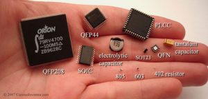
SMDs attach to the surface of boards, not through holes like older components.  They are much smaller and more difficult to physically handle.  A different technique has to be used.

Due to the larger size of through hole components, they are much easier to solder than SMDs.  It would be easy to lose a SMD 402 resistor since it is so tiny.  Cough on it and it is gone. 🙂

There are a number of different types of solder usage.  Electronics, jewelry, and plumbing are some of the most common.  But right now we are talking about  soldering for electronics.   In the electronic soldering category, there are basically two types of solder used, lead and lead free.  You can check out what wikipedia says about solder.

As wikipedia notes, lead-free solder widely came into use around July 1, 2006 due to EU directives prohibiting the inclusion of significant quantities of lead in most consumer electronics produced in the EU.  In the US, manufacturers may receive tax benefits by reducing the use of lead-based solder.  Further more most lead-free replacements for conventional 60/40 and 63/37 tin/lead solder have melting points from 5 to 20 °C higher (that’s 41 to 68° F).

For the past few years when I have had to solder something or the other, I  have used lead free solder.  The solder that I use is some no name stuff that I got from Banggood in China.  I must say that Banggood certainly has been adding more things to list of offerings that appeal to makers and hobbyist.

Not everybody I know likes to use lead free solder.  It is harder to use.  My friend David said that he has only used lead free solder once and hated it.  He only uses tin/lead solder, since he doesn’t have to use the lead free stuff, which has such poor adhesion.  The soldering station he uses is a Weller WLC-100 40w unit with adjustable heat, but no thermometer.  He uses it on hottest setting as he wants to solder as quickly as possible.  He says that the lower the temperature, the longer it takes the soldered area to get hot, which means the temperature gradient is lower into the part, so the part gets hotter.  If you do it fast, the part is not yet hot when you take the heat back off.  Too slow and the part can overheat and get damaged before you can even solder it.  A lot of parts are not very heat sensitive, but some are.  So he treat them as if they all are heat sensitive and he has never have any part issues.  While he has never had a very good soldering station as he says, he still makes some great stuff using the one he has.

That brings up and interesting point.  While the Weller WLC-100 is a popular soldering station and fairly inexpensive at $40 from Amazon, there are better soldering stations available.  The Hakko FX-888D 70w unit is better.  But it is more expensive costing around $96 at Amazon.  Abut two and a half times the cost of the Weller.  Note that Weller does have a soldering iron that is comparable to the Hakko FX-888D.  It is the WESD51 and it costs around $138 at Amazon.  Weller also has the analog version of the WESD51 which is called the WES51 and costs around $98 at Amazon.  But the Weller units are only 50w compare to 70w for the Hakko.  Hakko does not sell the analog version of their FX-888D.  It was discontinued when the FX-888D was released.   I have a Hakko FX-888D myself.

The higher wattage of the Hakko along with its high-quality ceramic heating element allows this soldering iron to heat up quickly.  It reaches 350 °C (662° F) in just under 1 minute and heats consistently for long periods. This makes it well-suited for big projects that require extended soldering.

While having a Hakko FX888-D won’t make you better at soldering, but it can certainly help.  Being able to reliably set the tip temperature is a must I feel, especially when you are using lead free solder.  David knows his soldering station well and also has been soldering for long long time.  But he also is using tin/lead which adheres a lot better.  He can reliable use his technique of setting his Weller station to its max setting, heat the joint quickly, apply the solder, and finish up.  It is all about working quickly.

The higher temperature you use will speed the oxidation of your iron’s tip.  One source that I came across on the internet mentioned that for the Hakko FX888-D when using lead free solder you will typically have the temperature set between 700 to 725 °F (they use 716 and 725 °F).  For tin/led solder the temperature can be set to 650 °F or even as low as 550 °F for most work.  But the hotter temperature allows them to get in and out quickly like David does while using his Weller WLC-100.     So when using lead free solder you most likely will be running the iron hotter than if you were using tin/lead.  That means that you need to need to keep the tip of your iron clean and well tinned.  If the tip becomes too oxidized, you won’t be able to keep solder on the tip.  The solder won’t wet or flow onto the tip, but it will most likely ball up and fall off.  With an oxidized tip you won’t be able to transfer heat to a joint in order to solder.  This tip needs some serious cleaning.

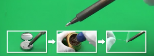
So how do you clean it if it gets like this?  Get some tip tinner/cleaner. Have your soldering iron at a normal operating temperature and then wipe the oxidized tip into the little tin containing tip tinner/cleaner for a few seconds until the bright tinning surrounds the working end of the tip.  Next wipe of the tip with your cellulose sponge or brass wire sponge.  Then reapply solder to the tip.  The solder should once again wet or flow nicely on to the tip like when it was new.  You are good to go at it again.  Make sure you close up your tip tinner/cleaner after you have finished with it.  It will dry out if you don’t and will be harder to use.  Please note that you should not use tip tinners unless necessary.  They will erode the tip plating incredibly fast if used too often.  Which is typically any more than once or twice a day.  Ideally, you should never use them.  You want to maintain a small amount of solder on the tip at all times to prevent the oxidation condition.

So is soldering easy?  For the most part it can be.  You just need to keep your iron’s tip clean and tinned frequently.  Don’t allow your tip to oxidize which will shorten its life.  In a nutshell it is all about tip care.  You have to get into a set routine while soldering that will allow you to do that.  Something like solder a few connections and then clean and tin the tip.  Repeat the process.  Like in all things, where in order to be good at it, you need to practice.


Place the tip on the joint to heat it up.  Note that you must push against the joint with some force. Not much, perhaps on the order of one-half a pound of force.  Beginners often just very lightly touch the joint with the tip.  Apply the solder to the joint. If the joint is hot enough, the solder will wet or flow onto the joint.  Feed the solder into the joint until you have enough to fill any gaps.  But don’t over do it since too much is not good.  Remove the solder when you have a sufficient amount on the joint.  After you have removed the solder, then remove the tip from the joint without shaking or bumping the joint.  The whole process from placing the tip on the joint to the removing the tip from the joint can typically take two to 4 seconds.  It all depends on a few variable like how much power your iron has and the size of the solder joint.

Typically clean your tip with the brass sponge or cellulose sponge.  Then apply solder to the tip and clean the excess off with the brass sponge again.

You might notice while watching soldering howto videos, that the presenter will briefly apply a bit of solder under or near the tip where it touches the pad and the component lead.  This creates a thermal bridge that helps in the heat transference from the tip of the iron to the joint.  Then they apply the solder to the other side of the component lead or pad.  Then they fill the pad with solder like usual.

In the videos I wasn’t exactly sure why they were doing that because from what I had read in the past, you are suppose to heat the joint and not the solder.  I guess if the tip isn’t sufficiently wetted, then that creation of the thermal bridge helps.

There are things about the process of soldering that some basic guides don’t mention.  Things like sizing the tip to the area of the joint you have to solder.  The tips come in different sizes to match the work area.   When using copper braid to de-solder joints, you need to make sure the tip is free of oxidation.  If it isn’t, then the heat won’t transfer to the wick and the solder from the joint won’t flow into the wick.

This was not intended to be an introduction to soldering.  This post is just my observations from trying to get a handle on using lead free solder while soldering.