It has been a while since my last post. I hadn’t worked on anything in a while. I am continuing with my quest to get my 3D printer to print correctly. I had been trying to get the printer to print without having the filament ball up on the nozzle.
I ordered a new extruder assembly from the MendelFlex guy, but not sure when he will finish the batch he is working on. It has been a while. Any day now.
The OVM20 board has had some issues with the micro usb connector. It kept disconnecting. Very hard to upload an updated sketch when it keeps disconnecting.
I tried to use an avr programmer I had to program the OVM20, but it failed on the verify of the write to the on board flash. So I removed the OVM20 and went back to a two board setup using a Mega2560 and a Ramps 1.4. I am using the Ramps 1.4 board that I got from the maker of the OVM20 board. His boards are well made, inspite of the usb connector issue I am having. On his next go around with the design of the OVM20, I suggested that the board not use a micro usb connector but a usb b connector like the mega uses and other boards use. Those connectors don’t allow the cable to wobble when plugged into it.
After I reinstalled the boards, I had to adjust the step settings for the three axises and the extruder. They were off now because the OVM20’s settings for stepping is hard set to 32 steps while the Ramps 1.4 I have it set to 16 steps. Once the movement on the axises was set, I adjusted the settings for the extruder. I heated the hot end up to 185 C and then extruded 100mm of filament. The amount extruded was off so I had to adjust it and try again. I had it set correctly after two tries.
The plate glass did not sit completely flat in its 4 corner brackets. On two corners they lifted up a bit. I believe that this was affecting the print adhesion, but probably not the only thing. I got 4 large binder clips and used them to hold the glass in place. I also got a simple bed leveling sensor to help with things.
I changed the marlin firmware to add in bed leveling in the menu options. I couldn’t get the simple bed leveling sensor to work out. The bed isn’t level. I put the binder clips in place, but they did not seem to help. I going to change out the print bed. I have a 4mm thick aluminum plate that I can use. It was made to match up with the MK2b size heaters. I will put a PEI sheet on top of the aluminum plate and print on that.

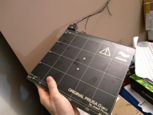
After thinking about it for a while, I won’t be using the aluminum plate and MK2b combo. I have a genuine MK42 heatbed from Prusa Research that I will use. It also works with a Pinda probe which I have. The MK42 is an aluminum plate with a built in heater. It also has a PEI sheet on top. One bad thing is that I need to rearrange the electronics since the power cable for the MK42 won’t reach where the electronics are currently located.
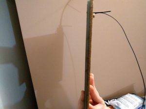
I had some cork backing that I put on the bottom of the MK42 for added insulation. I will have to mount the Pinda probe later after I figure how I am going to attach it.
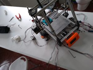
Before I mount the MK42, I have to move the electronics. I swapped the two z motors also because the wiring on one motor was cut short before to reach the electronics near it.
Because of the heatbed’s power cable, the power supply would have to be moved also. I removed the PS along with the Mega2560/Ramps setup. I then installed the new MK42.

I moved the PS and the electronics into their new positions.
Lastly I hooked up all the wiring for the stepper motors, the end stops, the heatbed, the hot end, the thermistors, and then the fans.
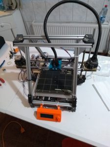
Back on the testing center table ready to see how things go.

That’s all for now folks!