
The other day I did some work on the MendelFlex. I received the smd leds and resistor that I needed. I had to replace the Mk2a heatbed with an Mk2b heatbed. The reason was that I had used standard through hole leds and resistor on the Mk2a. The side that was against the build plate was not smooth and flat due to the soldered ends of the components. The Mk2b has areas on both sides which allowed me to attach the smd leds and resistor along with the power connectors on the side which won’t be against the build plate. The Mk2a will work fine with the aluminum plate that I have which has a rectangular cutout just for this purpose.
I soldered the components and power connectors to the board. I attached the theremistor for the heatbed again. I got everything hooked up to the printer and the heatbed was working fine with the led coming on like it should when power was going to it. I used pronterface (aka printrun) to test. I turned on the heatbed to check how it was heating. According to the pronterface and the lcd on the printer, the heatbed wasn’t getting hot. But the hot end was getting hotter. Well, the theremistor for the heatbed was plugged into the connector on the ramps where the connector for the hot end should have gone. I shutdown the printer and then switched the connectors. Tested it again and pronterface and the lcd on the printer indicated that heatbed was getting hotter. Then I set the temperature on the hot end and that too was getting hot.
Next I started checking the x, y, and z axis movements. While the movement for the x and y axis seemed to be ok, the z axis movement was not right. For 100mm of movement, it was only moving about 25mm. So I looked on the web to figure out the issue. It had to be something in the Marlin settings. The DEFAULT_AXIS_STEPS_PER_UNIT value for z in the Configuration.h file needed to be changed. The value was set to this:
#define DEFAULT_AXIS_STEPS_PER_UNIT {80,80,400,1900}
The values are for x, y, z, and e (extruder). Not really sure what the extruder needs to be set to right now, but will figure that out when I get to that. Since my z movement was only a quarter of what it should have been, I changed it to 1600 in the Configuration.h using the Arduino IDE. I then compiled the sketch. Once I got a clean compile, I tried to upload it to the Arduino Mega on the MendelFlex. The sketch on the Mega was erased but the new sketch was not uploaded. Everytime I tried to upload the sketch, I kept getting an avrdude timeout error. I looked on the internet but couldn’t find a solution. I gave up for the night. Today I tried again. This time I tried to load the sketch to a different Arduino Mega 2560 that I had. The same thing happened, I got the avrdude timeout error. So whatever the problem is, it probably wasn’t the board. I was using the Arduino IDE on MBP. I have the Arduino IDE on my Win 10 laptop too, so I tried to upload the sketch to the spare Arduino Mega from there. Well it worked. I was running version 1.6.9 of the Arduino IDE on the Win 10 and the version of the Arduino IDE on my MBP was 1.8.4. I tried loading the sketch from my Win 10 laptop to the arduino mega for the printer and it did upload. I had to recompile and upload a few times while I fooled around with the lcd setting in the Configuration.h file before I got the lcd to work. But I got it working again. Not sure what the heck the issue is with the newer ide. I will leave that question unanswered for now.
Now I can see how the z movement goes. If you remember I changed the axis steps value for the z to 1600. While I don’t want to use my MBP to compile a sketch, I can still use pronterface to test the movement of the x, y, and z.

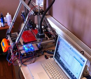
In the above picture I set x to 100, y to 100, and z to 100. It looks good. I homed x, y, and z to zero, then I took some measurements to make sure the movement is correct. The z movement was correct. The x and y were correct also. I still might have to tweak things a bit. But things are progressing.