From 12v to 24v

Sometimes you need to pivot when things aren’t going as planned.  The original P3Steel had a 12v system which only allowed the heatbed to reach a temperature of 60°C for PLA, but not high enough for filaments like PETG.  I  made the command decision that the P3Steel needed to be scrapped with some of its parts being donated to a new build.  Essentially another P3Steel build but running on 24v instead of 12v.  It is a P3Steel but with an Orballo black frame.  Very similar to the P3Steel with the blue frame, but this frame will accept a larger heatbed that fits the Prusa MK2 and MK3 series printers.   The heatbed on the new build is actually wider, but you can’t tell from the two pictures.

This system is essentially a Prusa MK2.5S with a Mini Rambo 1.3a running the latest Prusa firmware 3.14.2 (as of this date).  The difference is that it will be using a 24v heatbed and a 24v hotend.  But it is using two 5v fans like the MK3S does.  Plus I added a E3D Revo V6 hotend  just like I did for the MK3S.  I will be able to swap out the hotend very quickly.  I was able run through most of the builtin Prusa tests, but failed in a few.  That is due to the frame not being the same exact size as the MK2.5S frame so the Y was a little bit off and as was the Z.  But all the movements are correct and it printed a nice first layer test.  I have no trouble getting the heat bed to 70°C or higher.  Looking forward to fully integrate this printer into the lineup.


Anycubic Kobra 3 Max Combo

Just received the Anycubic Ace Pro that I ordered from Amazon.  This along with the Anybcubic Kobra 3 Max will complete the Combo.  They didn’t have the Combo (Kobra 3 Max plus the Ace Pro) available for sale with free shipping at the end of March, so I ordered just the Kobra 3 Max which was on sale and included free shipping.   I ordered the Ace Pro a few weeks after the Kobra 3 Max.  It wasn’t on sale but it still had free shipping.  Now both the Kobra 3 Max and the Ace Pro don’t have free shipping.  And the Kobra 3 Max isn’t on sale.  If I bought both today, it would have cost me $215 more.  That’s a lot of filament there. 😉

The build volume of the Anycubic Kobra 3 Max is massive.  It measures 420mm x 420mm x 500mm!  It dwarfs the 250mm x 210mm x 220mm build volume of my Prusa Mk3x.  Not really sure the build height of my MK3X is really 220mm.

When I received the Kobra 3 Max, I checked the box for damage.  There wasn’t any noticeable damage, but the box was coming apart on a corner.  It looks like the he shipper applied extra tape to fix that.  Nothing was damaged in the box.  The packaging inside was good.  I had watched a few videos prior to receiving my printer so I knew what had to be done.  I opened the manual and proceeded to follow the directions to assemble the printer.  The printer is not a kit like I have dealt with before.  The Z axis was removed from the base and packed flat on the base.  Not loosely packed but it was bolted together with the base to make one unit.

Following the directions I was able to assemble everything.  From watching some of those YT videos on the Kobra 3 Max, I was able to fix a few issues that other people had.  Mostly it was making sure things were tight.  I did contact Anycubic support for a few issues.  From looking at the manual it seemed that there was something to be set if you were using 220v instead of 110v.  For this printer you just use the appropriate power cable, plug it in, and it automatically senses the current you are using.  The other issue I had was that the feet weren’t level on the table.  My table was a bit off, so I put the printer on a glass surface.  It was still a little bit off.  Anycubic support got back to me and send me a nice instructional email on how to fix the issue.  They also solved an issue I had with not being able to log on to my account at their Makeonline.com site. All in all, Anycubic support was prompt and helpful.  I went thought the various tests, but haven’t attempted to print anything since I was waiting on the arrival of the Ace Pro unit.

Right now I am printing some parts for a mod of the Ace Pro.  The mod adds a PTFE tube to each of the 4 filament inputs in the Ace Pro.  This mod will eliminate wear to the input pads due to friction caused by the filament rubbing on the pad.  This will also help insure that the filament feeds into the Ace Pro without any kinks or twists that will cause a jam.  For each input on the Ace Pro, two parts will need to be printed.  A new input pad and a guide at the end of the PTFE tube.  Here is a link to the new input pad.    This input pad uses PC4-M10 Pneumatic Fittings.  It was a remix of the original design which uses PC4-M6 Pneumatic Fittings.   I got a set of fittings from Amazon which had both sizes.  The remix pages doesn’t have a guide head STL file since he now thinks that the original guide head is better.  So I had to get it from the original design page.  For the PTFE tubes, the length is 14cm (5.5 inches) long.  I printed out the STL files, cut the PTFE tubes, and installed the PC4-M10 fittings into the replacement inputs.  The tubes need to stick out of the input pads just a little bit like the original, due to the input area inside of the Ace Pro under the cover piece.

It is all ready to go.  Now I have to finish up with the Ace Pro setup and integration with the Kobra 3 Max.


P3Steel Tuning

In a prior post I talked about my 3D Printing Journey.  One thing I talked about was trying to set the E axis steps for the P3Steel because the extruder was having an issue and was clicking while it was feeding the filament.  I have finally got back to tuning the P3Steel.

I thought it would be a good idea to check what were the settings for the Prusa Mk3x.  This should give me a good baseline since I am using the same z stepper motors and the other stepper motors are very similar.  The extruder setup came from parts for an Mk3 using the Bondtech gears.  By using Pronterface and connecting to the Mk3x, I will be able to use the Marlin M503 command to see what the settings are.  Then I will edit the Marlin files for the P3Steel and set the appropriate values to match.

Issuing the M503 command I can see that the default axis steps per unit values for the Mk3x are Y=100, Y=100,  Z=400, and E=280.  First I did the classic extrusion test where you make a mark 120mm from where the filament goes into the extruder.  You then extrude 100mm of filament.  You next check to see how much was extruded by by checking your mark at 120mm with the point where the filament goes into the extruder.  Ideally the distance should now be 20mm.  If you have less than you are under extruding.  If you have more, then you are over extruding.

Well when I first did the test, that 120mm mark disappeared into the extruder and filament kept feeding into it for a while.  So I then marked off 3 segments of 100mm each and ran the test again.  Well, two of those marks disappeared into the extruder.  I was able to see how much was extruded.

I edited the Marlin Configuration.h file to make a change to the E value for the default axis steps per unit.  I compiled the firmware and loaded it to the P3Steel.  Each time I make a change to the firmware, I change the output name of the printer (“P3Steel-1.8”).  That way I not it has changed.  When I ran the test again, the same thing happened.  A lot more than 100mm of filament was pulled in.  On the printer you can check the configuration settings.  The value that I thought I changed was the same.

The settings for the P3Steel were Y=100, Y=100,  Z=400, and E=1900.  The value for the E value wasn’t 280 like I had set it to.  A little bit of head scratching here.  What happened I thought.  Well the magic of EEPROM happened.  Even though the name changed, the changes I made were now part of the default settings and not the current settings.  So in the LCD menu for the printer, I loaded the default settings and my change was there.  I then saved the settings to the EEPROM to make sure they would stay there.  I marked 120mm on the filament and ran the test again by feeding 100mm in to the extruder.  I measured what was left and it was 20mm.  So it was a success.

Quick note here.  In my prior post when I was trying to work on the extruder clicking issue, I had changed the E value to 575.  It seemed to have helped, but I did not run an extrusion test, nor did I check the axis steps value for the E.  More than likely it was still 1900.

In tuning a 3D printer, in addition to the E step calibration, there are a number of other things that should be looked at.  Updating your firmware can help issues with know problems.  So check with the kit supplier (Prusa, etc.) or with the project that produces your firmware (Marlin, Klipper, etc.).

Check the mechanical components of your 3D printer.  Make sure all the fasteners are tight.  The belts should be tight (but not too tight).  The pulleys for your belts shouldn’t move on the motor shafts (check and tighten the set screw).  If you have wheels on your 3D printer, make sure they are properly tightened to prevent wobble and wear.  Regular lubrication is needed on any of your lead screws, guide rods, or other bearings to keep the parts moving without friction.  SuperLube synthetic grease is good for this.

Print shifts to the left or right can be caused by a loose belt or a broken pulley or a free spinning pulley on the X axis.   Print shifts to the front or rear can be caused by the same issues but on the Y axis.  I had an issue once on a print where on the last few layers, the print shifted to the left right a bit.  I was able to use the print ok, but the guide pulley on the X axis broke which caused the shift.  Sticking leads screws or friction on the guide rods can cause layer issues due to the Z not moving smoothly.

The stepper motors of the 3D printer can cause EMI or RFI interference issues.  I seem to be having that with the output on the LCD screen for my P3Steel.  The cables aren’t shielded at all.  One possible solution is to get some snap on ferrite filter cores for the LCD cables.


Soldering Temperatures

What’s the correct temperature to set your soldering station to?  I am trying to figure out what temperature presets should I use on my Hakko FX-888D.  I can have up to 5 presets.

According to Collin’s Lab Notes, the short answer is for leaded solder to set your iron to 650°F/350°C.  And for lead-free solder to set your iron to 750°F/400°C.  The long answer is that it depends on two different variables, tip size and joint size.  A larger tip is better at transferring heat, so you can use lower temperatures.  A smaller tip transfers less heat so you need more heat.  On the other side of the equation, a larger joint needs more heat so a higher temperature setting is desirable.  A smaller joint heats up faster and it needs less heat, so a lower temperature setting should be used.  Keep in mind that higher temperatures affect the life of your soldering iron tips.  So when in doubt, use a lower temperature and increase the temperature when needed.

The HAKKO Knowldege Base also provided good information on the different optimal soldering temperatures for leaded solder and lead-free solder.  While I am providing the information for the link, I am going to present the information here from the knowledge base.  But in a nutshell, the optimal temperature setting should be high enough to achieve a soldering connection at 50°C above the melting point of the solder, while also adding in more heat (70°C to 100°C) for a heat reserve for quick thermal recovery of the tip after a connection is made.  This recovery range factors in the performance of the soldering station and type of solder used.  Here is a chart for reference on the melting points of various solders.

As a general rule of thumb, the optimal soldering temperature should be high enough so that when making a solder connection, the solder is approximately 50°C above its melting point.  The set temperature for a soldering station should be an additional 70°C to 100°C higher to provide a heat reserve for the quick thermal recovery of the tip after the solder connection is made.  The performance of the soldering station used and the type of solder used will determine the optimal soldering temperature.

For example, lets look at the melting points of common solders:

  • Tin/Lead (Sn63/Pb37) – 183°C
  • SAC 305 (Sn/Ag3.0/Cu0.5) – 220°C
  • SN100 (Sn) – 232°C

Now let’s add the 50°C we need for making a good soldering connection:

  • Tin/Lead: 183°C + 50°C = 233°C
  • SAC 305: 220°C + 50°C = 270°C
  • SN100: 232°C + 50°C = 282°C

We now need to consider the type of soldering station we are using.  If we are using a Hakko 936 Soldering Station which has very good performance, we should add approximately 100°C as the heat reserve for quick thermal recovery.  The resulting temperature settings are:

  • Tin/Lead: 233°C + 100°C = 333°C
  • SAC 305: 270°C + 100°C = 370°C
  • SN100:  282°C + 100°C = 382°C

As you can see, switching from tin/lead solder to lead-free solder requires a higher optimal temperature setting.  But before you raise your set temperature, you must consider the setting you are currently using, and the performance of the soldering station.  Most Hakko soldering stations are typically set at about 399°C (750°F).  Considering that, the optimal temperature setting does not need to be adjusted when changing from tin/lead solder to lead free solder.

Now let’s look at the optimal temperature settings if we were using a high performace soldering station such as the Hakko FX-951 Soldering Station.  Because of the performance of this soldering station and the thermal recovery performance of the composite tips, we only need to add 70°C as the heat reserve for quick thermal recovery.  The resulting temperature settings are:

  • Tin/Lead: 233°C + 70°C = 303°C
  • SAC 305: 270°C + 70°C = 340°C
  • SN100: 282°C + 70°C = 352°C

Again, considering that most Hakko soldering stations are typically set at about 399°C (750°F), we do not need to raise the set temperature.  In fact, we can use a lower set temperature which will help extend the service life of the soldering iron tip and reduces the risk of damage to the PCB and components.

That wraps up this post.

Hakko FX-888D Setup

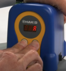
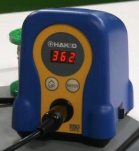
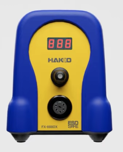
Recently i noticed that Hakko has released a new version of their FX-888D soldering station.  The new model is the FX-888DX.  The main difference I can see is the addition of single adjustment knob which replaces the two adjustments buttons that the FX-888D had.

The new model can also use an optional 95w iron for more demanding soldering work.

I have the FX-888D and it is good soldering station.  It is 65w and has a temperature range of 120°F to 899°F (50°C to 480°C).  The time to reach 660°F (349°C) is 26 seconds.  A good soldering station.

I will go through the setup of the FX-888D in order to document the process.  There are a four parameters that you can change in the setup .  You can choose either Celsius or Fahrenheit as the display temperature.  You can set a base temperature so that an alarm will sound if the station doesn’t go pass this value.  You can choose between normal mode or preset mode.  Preset will allow you to set a number of different temperature presets.  And the last thing is setting a password.  This probably could be useful to people.

In order to get into the parameter settings, press and hold the UP button while turning on the FX-888D.  Let the button go when the display lights up.  Next 01 will flash to indicate that you at Preset 01.  Press the Enter button to allow you to set the display temperature scale to either Celsius (C) or Fahrenheit (F).   Pressing the UP button will cycle through C and F.  By pressing the Enter button, you will set your chosen temperature scale.  The 01 will be flashing again.  Press the UP button to go to the next Parameter which is 03.

Parameter 03 is to set a base temperature so that an alarm will sound if the station doesn’t go pass this base value after a certain time.  We can press the Enter button to go into this mode to set the desired value.  Using the UP button and the Enter button will allow us cycle through the digits to set the desired value. Pressing the UP button at the flashing parameter number takes us to the next parameter.

Parameter 11 is next and it allows us to choose between normal mode or preset mode.  Normal mode is 0 and preset is 1.  Normal mode just has one preset temperature wile Preset mode will allow you to set a number of different temperature presets, up to 5.  We don’t each preset temperature value here, we just set the number of presets.

Parameter 14 is next and it is about setting a password.  This probably could be useful, but I am not going to use it and not going to describe it here.

When we are done changing the parameters that we want, we press and hold the Enter button for a second.  A Y will flash on the display.  If we want to save the values, we will press enter again.  If we hadn’t wanted to save the values, when the Y was flashing, we would have pressed the UP button to cycle through to a flashing N.  Then we would have pressed the Enter button to not save the changes.

How to change your set or preset temperatures.  For example if the default set value was 750 and you wanted to set it to 660.  First press and hold the Enter button.  The hundreds digit on the display will begin to flash.  You will use to UP button to cycle through to the digit value you want.   In our example the 7 is flashing and I would press the UP button, scrolling through until the 6 is displaying.  Press the Enter button to move over to the tens digit.  Press the UP button to scroll through to the desired value.  Press the Enter button to move over to the ones digit.  Make a change to this value if needed by using the UP button.  Then press the Enter button to finish.

This will work for if you have a number of presets.  For the presets you will use the UP button to select the various presets, P1, P2, etc. up to P5 if you have 5.  Press the Enter button to set the iron temperature to the preset that you have chosen.  When it heats up to its value, you can do the change as described prior.

From time to time you probably want to dial in or adjust the set temperature on your FX-888D, so that it will be more accurate.  You will need a way to measure the temperature of your tip.  There are tip temperature measurement tools.  Hakko has the SG-100B.  With the iron on and it is at its set temperature, measure the tip temperature with the tool.  Once you do that, you will press and hold the UP button on the FX-888D to get into adjustment mode.  Then you set the value to the temperature that you measured with the tip temperature measurement tool.  The UP button will cycle through the digits.  The Enter button will take you to the next digit and will also exit when you are at the 1s digit.

If for some reason, you made mistakes when you made your changes, you might want to do a factory reset. Here is how to do a factory reset on your FX-888D.  When the power is off, press and hold both the UP and Enter buttons.  Turn on the power.  When the power comes on your will get a flashing A which means Asia.

Press the UP button one time to get a flashing U which means US.  Press the Enter button to choose this selection.  The FX-888D has been reset to its factory settings.

Here are the video links where I got my information from.  There is no guarantee that any video that I link to will be available later, so I tried my best to document the information.

FX-888D Setting and Adjustments document.

Here is a very short video by Hakko on the parameter settings on your Hakko FX-888D.

Here is another video where we are shown how to set the different parameters.

Here is the video by Hakko where I got the information on changing vs adjusting the soldering temperature.

Here is a video by Hakko on setting the Preset Temperatures.

Here is a short video by Hakko on setting the Temperature on your FX-888D.

Here is a short video by Hakko on using the Adjust mode.

How To Set and Use the Password Lockout Feature on your FX-888D.

My 3D Printing Journey

My 3D printing journey has been a long one.  I am certainly no expert, but I have learned a lot.  A lot of the info is from my favorite Youtube 3D printing channels while the reset has been on various forums and internet searches.

My first 3D printer was the MendelFlex, which I have talked about in this blog.  I had some success with it, but ultimately I dismantled it for parts.  My second 3D printer was a P3Steel.  I got the 3mm steel frame cut using the design files from the Thingiverse P3Stee design named the “Leonardo” .  I modified the original DXF files and added a mount for the 2004 LCD display which came from another P3Steel design.  The build turned out pretty well.  I am in the process of getting it working.  I need to finish calibrating the axis steps.  The setting of 1900 I had for the E step was much too high.  It caused the extruder to click while I was testing the filament feeding.  I set it to 575 and the clicking stopped.  But I will have to fine tune it.  Here are the youtube videos that describe the tuning process.  It is in two parts.  Here is part 1 and here is part 2.

My third 3D printer is my Prusa Mk3x.  Since most of the parts originally came from Prusa sans the frame pieces, have designated it to be Mk3x.  In the firmware it is a Mk3S.  I added modifications to the X axis and Y axis by adding Hiwin linear rails to the printer.  I also added an E3D Revo V6 hotend to facilitate easy nozzle changes.  This modification will eliminate any chance of filament leaking in the heatblock since the nozzle and the throat tube are one piece on the Revo.  I have been getting pretty decent prints.  Not perfect but I have remember to dial in the settings for each filament.  I am printing parts for other printers.  Replication sort of. 🙂

Compiling Marlin with Visual Studio Code

Versions 2.0.9.7 and 2.1.2.1 of Marlin support ARM in addition to AVR.  You can use the Arduino IDE or PlatformIO to compile and load the firmware to the device.  I already mentioned the trouble I had with the latest version of the Arduino IDE, so I thought I would look into what PlatformIO was.  Well I was pleasantly surprised to find out that PlatformIO is an extension available for Visual Studio Code (VSCode).  VSCode is like a Swiss army knife when it come to development and I do have it installed.  There are a number of interesting extensions available that are really useful.  IBM has an extension called Z Open Editor that provides tools for IBM Z development along with COBOL, PL/I, HLASM, and REXX language servers.  The old mainframe comes alive and is almost modern in this extension.  Almost. 🙂  But it works really well.

After installing the PlatformIO extension and having already downloaded Marlin versions 2.0.9.7, I went to work on getting it ready for my MendelFlex.  You go through the same process of editing the Configuration.h file with the values that you need for your printer, and then compiling it.  Once you get a clean compile, you can upload the compiled Marlin to your printer.  I used the Configuration.h file that I edited for Marlin 1.1.9.1 as a reference.  While things were similar for the most part, there were a few things that were different.  I was successful in compiling and loading the binary to the MendelFlex, but LCD screen on the printer didn’t refresh itself and displayed blocks.  I wondered for a few minutes on what happened and then I realized that I must have forgotten to set the LCD screen in the Configuration.h file.  Sure enough it was not set and the SD card setting wasn’t set as well.  Set those two items, compiled, and uploaded the Marlin binary up to the printer.  The LCD screen refreshed after the upload and displayed the information I expected.  Success!


Updating Marlin on my MendelFlex

While doing some research on updating the Marlin firmware on my MendelFlex, I came across a few good resources.  First I need to save my current settings by using a program like Pronterface.  Inside of Pronterface I connect to the MendelFlex and then send a M503 command which tells the printer to list its settings.  I then copy and save that information into a file for later use.  Then I edit the Configuration.h file and change certain settings.  I will also be using my old Configuration.h file for reference.  Unfortunately it was not the latest file.  After editing the file I need to open Marlin file in the Arduino Ide.  I downloaded and installed version 2.2.1 of the ide.  While I attempted to load up the Marlin files in the ide, it only got so far and then the ide froze.  In fact my laptop froze and I couldn’t even Ctrl alt delete it!  Tried it again running the ide as Administrator but same thing happened.  I tried down loading the latest nightly version (which is like version 2.2.2) of the Arduino Ide and the same thing happened.  Was looking online to see if anyone else had this issue.  I haven’t found a good solution.

I decided to install an earlier version of the Arduino software.  Version 1.8.19 doesn’t have the Ide moniker tagged to the name.  I was able to verify it worked successfully with Marlin 1.1.9.1.  While it did run, I did have two errors I needed to fix.  After I fixed them, I ran the verification step and got a clean compile.  After I that, I was able run the load process and was successful putting Marlin 1.1.9.1 on to the MendelFlex.

There were a few more things I had to set in the configuration file.  I thought I enabled the SD card reader, but I hadn’t.  I am at a good point now with my settings.  I am expecting a filament dryer this week sometime.  I will need to make sure the 3mm filament I have for the MendelFlex is dry enough to use.  The filament picks up moisture over time and my filament is old.  This can cause trouble with your prints.  When I start printing, then I will make sure I have a good Z offset.  That’s all for now, catch you later.

Lazy Susan in the Workshop

I thought I would create a quick post about the Lazy Susan that I used in my post on my MendelFlex rewiring effort.  You might have noticed it in my Prusa MK3x post too.

I ran across a video on YouTube where they used a Lazy Susan while they were working on the hardware in their computer.  I thought that was a neat idea, so I looked into making a Lazy Susan for similar tasks.  I looked at a number of videos and found some useful information.  Adam Savage had a video where he talks about Lazy Susans and how useful they are.  But the Rockler base plate that he liked was more than I wanted to spend and I didn’t need something as heavy duty.  I looked on Amazon to see what suitable Lazy Susan base plates were available.  I determined that I wanted my Lazy Susan to have a platter of around 21″.  This size would be suitable for use with my largest computer case and also my 3D printers.

Here is the 12″ base that I eventually bought from Amazon.

The Lazy Susan really came in handy while I worked on my Prusa MK3x and on my rewiring effort of the MendelFlex.  It was easy to turn the printers around and work on them.  The MendelFlex is a bit heavy so being able to easily move it was very helpful.  It is a great thing to have in the workshop.  I highly recommend it.

MendelFlex renewal

After I finished with the build of my Prusa MK3x, I turned my attention towards my original 3D printer, the MendelFlex.  I needed to get it back to a working state and also improve its printing ability.  The first thing on the list was to fix the wiring.  It was a mess literally.

Plus I needed to repair the wires to the cooling fan on the printer because one of our cats decided to bite it in half.  They have a bad habit of doing the same thing to wires on earbuds, on USB cables, on ethernet cables, and other things.  We have had to put some plastic conduit around the cables to protect them.  I am going to be doing the same thing while I clean up the wiring.

Initially the ramps controller board on the printer was in a  different location.   It was in the area under the heatbed where the power supply is.  It made it hard to easily access the wiring on the ramps controller board.  So I moved it to the side of the printer.  I also fashioned a better cooling solution by putting a large fan over the ramps board.  The fan was something that I pulled from a power supply.  The fan has led lights that turn on when powered up.  Also the printer initially had a printed extruder carriage, but I replaced it with a metal carriage.  I replaced the bed assembly and heatbed with a bed assembly I had for a P3 Steel printer along with a Prusa Mk42 heatbed.  I added in a BLTouch sensor while doing all of that.  In the process of rewiring the printer I shortened a number of the wire leads.  One reason I kept them long was because I didn’t have crimpers for the connectors needed.

While working on the wiring I also replaced the Prusa MK42 heatbed with a Prusa MK52 heatbet with the removable metal plate.  The removable plate works great on my Prusa MK3x with good adhesion!

The last thing I did was to add a blower fan for print cooling.  I had to fashion a mount for it using parts that I had and a bit of hot glue.  By the way it did work after I finished all the wiring.  Using Pronterface I was able to send a M106 s127 command to the printer to turn it on and set the speed to 50%.  And then an M107 command to stop it.  I made extensive use of zip ties to keep the wiring harnesses in place and out of the way.

Wiring completed!

I did run into one small issue when I was testing out the electronics on the printer.  I was able to engage and move the X, Y, and Z motors from Pronterface.  But when I tried to home the printer, the Y motor didn’t respond for some reason. The X and Z were fine.  After close inspection I found out the the arm on the Y switch stuck into the closed position so the printer thought that Y was where it should be.  After fixing that, the printer was able to home just fine.

The next thing I will be doing is to update Marlin.  Currently I am running 1.1.6.  I will do some research and figure out which version will be best to upgrade to.

Until next time, Happy Printing!