Miyata 310 Completion

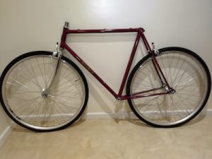
I had said that I was going to finish up the Miyata 310 build a few weeks back, but that week turned out to be really hot.  And the next week as well.  So I started working again on the build a few days ago.  I installed the handle bars, the shifters, the brake handles, and started to size the housing for brake cables and shifter cables.

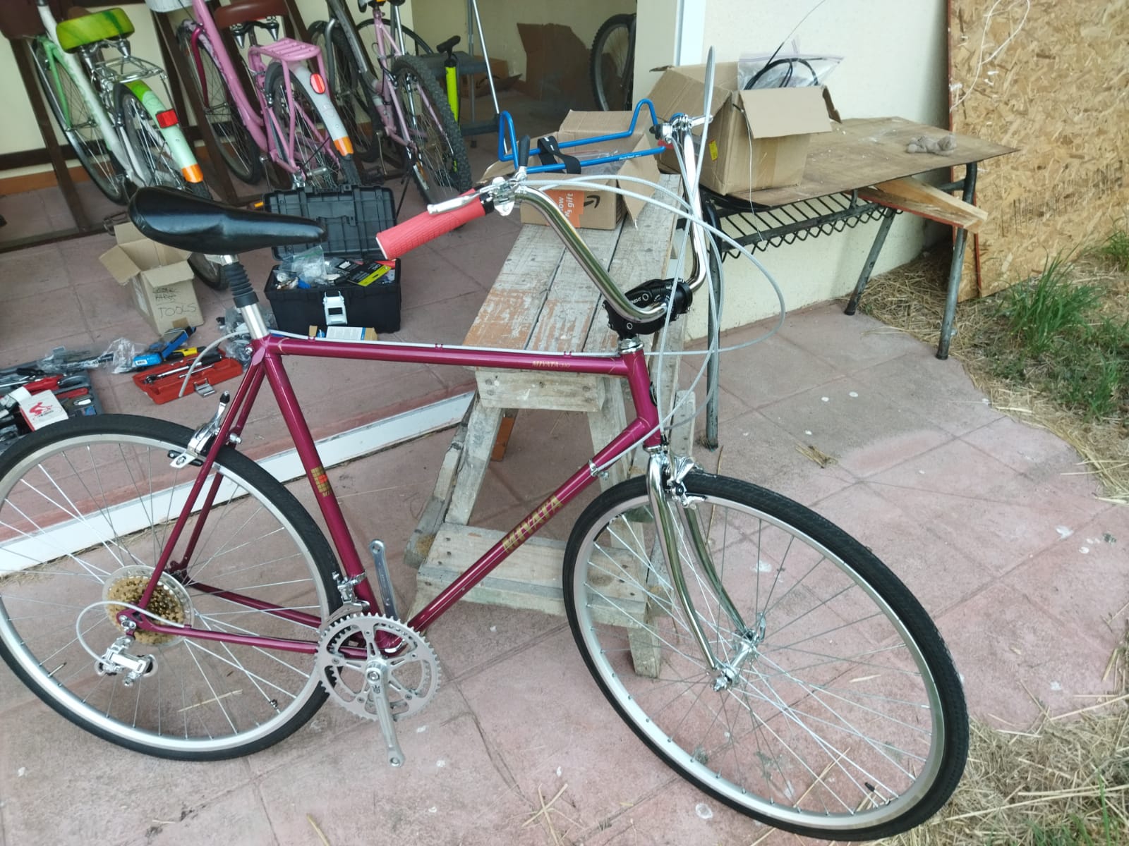
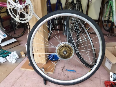
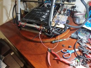
Today I finished cutting the cable housings to size.  Installed the brake and derailleur cables.  Here I am testing the movement of the derailleurs.

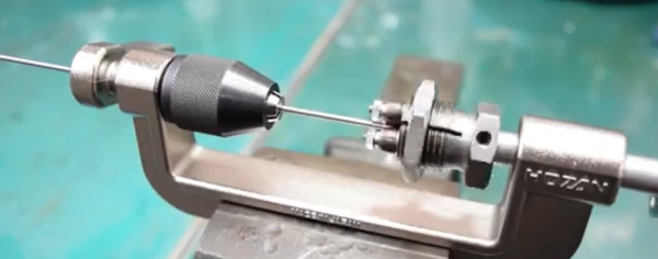
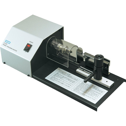
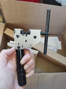
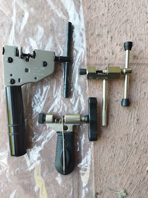
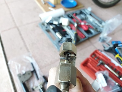
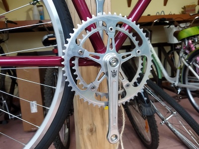
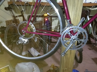
Now I am sizing and installing the chain.  I get to use my new Hozan chain tool.  There are three popular ways to size your new chain.  The first method was used by the late Sheldon Brown who was a well known bicycle mechanic and proponent of bicycling.  His website had tons of information on bicycles which I have used on a number of occasions.  His website is still maintained by his friends and family  To use the Sheldon Brown chain sizing method, you put the chain around the larges sprocket on your rear gears and then put the chain around the largest chainwheel on the front. Usually the front derailleur is shifted to the largest chainwheel, but I don’t see that it matters.  Don’t feed the chain through the rear derailleur, just make sure the derailleur is out of your way by shifting it to the smallest sprocket.  But make sure the chain fits on every tooth of the rear large sprocket that it can be on.  As the chain is around the rear large sprocket and the front largest chainwheel, pull the chain tight and find the closest matching link that you can connect to.  Then go back down the chain one link (maybe 2 if you are using a master link)  and at that point is where you will break the chain to size it.

The second chain sizing method needs the bicycle to be on flat and level ground.  You will feed the chain (which has the end that with accept the pin) around the smallest chainwheel on the front.  Next feed the other end of the chain around the smallest sprocket on the rear and also around and through the rear derailleur pickup wheels.  The chain end from the front will overlap the rear end of the chain.  Pull the chain ends gently together until the point where the cage of the rear derailleur moves forward.  At this point the chain coming off the rear derailleur ideally should have enough clearance not to rub against the top guide pulley on the derailleur.  Basically there should be a minimum of 1/2″ or 15mm gap.  On the overlap, you will break the chain at the point where the proper ends meet.  Note that if you are using a power link, then you have to go one link farther.

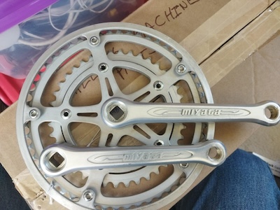
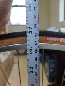
The third chain sizing method uses mathematics to calculate the chain length.  First you need to find out how many teeth your biggest sprocket on the rear  has and then find out how many teeth your biggest chainwheel on the front has.  Then measure the length of your chain stay which will be from the center of your rear wheel to the center of your chainset.  Measure it to the closest .125″ (1/8″).   I am going to do a calculation using the numbers I gathered from my Miyata which has a 53 tooth front chainring, a 34 tooth large rear sprocket, and a length of 16.25″ for the chainstay.  So the equation will be this for the Miyata:

(16.25 x 2) + (53 / 4) + (34 / 4) + 1

32.5 + 13.25 + 8.5 + 1 = 55.25″

This last method is especially helpful if you change you rear sprocket/cassette or your front chainwheel.  I was familiar with the first two methods, but not this third method.  I used the second method when I sized up the new chain for my Fuji build.  This time I am going to use the Sheldon Brown sizing method.  After I size the chain, I will compare the length that I come up with to the Math sizing method and see how close they are.

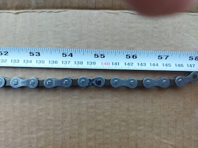
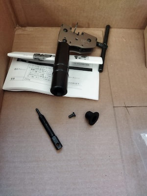
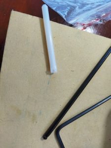
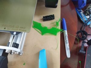
In the picture I made a mistake marking the link, I need to go over to the start of the next link.  So instead of 55″ it was almost 55.5″.  So 55″ and 55.5″ were still in the ballpark and very close to the measurement of 55.25″ that I calculated.

I was able to install the chain but had a little bit of trouble with the pin for the Shimano chain.  You are supposed to install a chain with the side that has writing on it facing the outside.  But this Shimano chain had writing on both sides, so I am not sure which side is suppose to face out in this case.

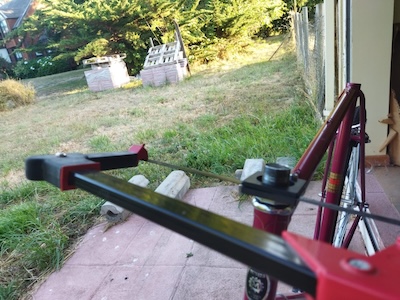
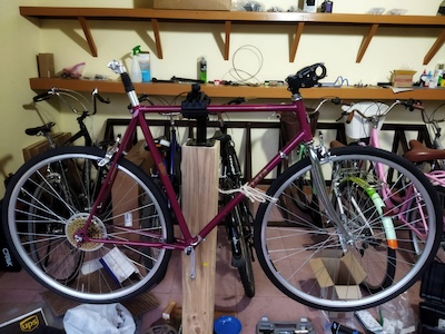
After I installed the chain I adjusted the high/low setting for the derailleurs.  Then I took the Miyata on a few test rides.  I moved the saddle back twice, a little bit after each of two short rides in the neighborhood.

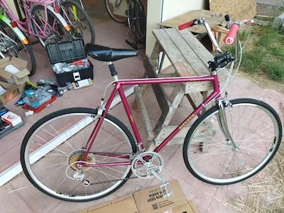
I completed about 99% of the build.  I need to install the toe clips and a speedometer I got for it.  But I will mark the build as completed!


Hozan Bicycle Tools

I don’t remember when I first became aware of Hozan Tools, but they have been around since 1946.  Besides making bicycle tools, they make tools for the electronics industry.

I have a number of their tools on my wish list.  The first one is the C-702 Spoke Threading Machine.  It is for use with round spokes.  There are 3 different cutting head sizes available (13, 14, and 15) depending on your spoke thickness.  You can cut a long spoke to the size you need and then use the C-702 to put threads on the spoke by turning the crank arm to do so.   It actually cold rolls the tread on to a spoke.  It comes in handy for those people who build a lot of bicycle wheels.  I have yet to build my first wheel, but that is one of the things I want to do.  You can get it on Amazon with one cutting head for around $119 USD which is cheaper than I have seen it on eBay.  Also on Amazon I have seen a cutting head is around $72 USD which is the cheapest I have found.

I saw a Hozan C-701 Spoke Threading Machine on eBay a while back.  It is motor driven.  I only saw that one unit there and someone snatched it up.  I saw a few videos of it in action and it was very easy to use.  It was around $450 USD on eBay which is a lot more expensive that you can get a C-702 on Amazon.  But I saw that a brand new unit with a #13 head at Modern Bike was $1500 USD but with free shipping!

The Hozan C-701 is not the most expensive Spoke Threading Machine I’ve seen online.  Wheel Fanatyk has a Morizumi that will cut and thread the spoke like you can get from the factory.  But it comes in at a whopping $3800 USD!  It is manual action where you pull a lever down and cut the spoke.  You then put the spoke into the threading area where you pull a lever down and push it back up for a finished spoke.  Really fast if you are producing a lot of spokes.  Not sure how many spokes you need to run through the machine before you get a return for your money.


Actually I forgot about the Phil Wood spoke machine which is an astronomical $7050 USD!  Not even going to show a picture for that thing.  I wonder how much the Phil Wood name adds to the price.

I got off the subject of the post, namely Hozan tools.  I have a number of cheap bicycle chain tools.  I have one that is part of a BikeHand tool set, and a few others that I picked up from various places.  All of them work but they are basically junk.  Which brings me to my latest chain tool, the Hozan C-371.

The C-371 is a heavy duty chain tool it dwarfs the other chain tools.  It is prescision made.  And at $74 USD it better be.

The BikeHand chain tool broke while I was using it a while back.  The metal piece that the chain fit over broke right off.  The metal isn’t very strong.


The handle of the C-371 holds a spare chain link press pin.

I am going to be using this tool when I install the chain on my Miyata 310 this week.


Miayta 310 Build Progress

Recently I spent some time working on the Miyata 310.  I was going to use a 7 speed IRD freewheel sprocket but unfortunately there was some binding between it and the frame.  So I had to use the gold 5 speed New Old Stock (NOS) Suntour freewheel that I had.  It looks good on the rear wheel.  I also added a Suntour chain guard that I picked up.  A lot of people remove them, but I added it for a retro look.

I got a Miyata crankset (made by Sakae) from ebay a while ago and I was going to install it on the bicycle.  But unfortunately when I tried to install it, there was some binding on the frame as well.  Because the mounting bolts for the small chainwheel are too far in, they scrape on the frame as the crank turns.  So I can’t use it.  It does look nice.  I guess I will create a shadow box for those parts that I can’t use.

So I am going to go with the Sugino Mighty crankset that I already had on the frame.  It is a nice crankset.  I believe I mentioned before that Sugino still manufactures cranksets in Japan.  Good quality parts.

Today I did a few things on the build.  I added gear cable guides, cut the stem of the fork to size, put in the seat post, put in the handle bar stem, and put on the derailleurs (both Suntour NOS).  I am using the handle bar stem that I previously had on my Fuji Team.  The seat post is a suspension post that I got in 26.6mm width to fit in the seat tube.  I got a tool from Stein Tool in the US for cutting the 1″ threaded fork tube to size.  Worked great. Used a file on the burs at the end of the cut.


This coming week I will go ahead and finish it up.

Compiling Marlin with Visual Studio Code

Versions 2.0.9.7 and 2.1.2.1 of Marlin support ARM in addition to AVR.  You can use the Arduino IDE or PlatformIO to compile and load the firmware to the device.  I already mentioned the trouble I had with the latest version of the Arduino IDE, so I thought I would look into what PlatformIO was.  Well I was pleasantly surprised to find out that PlatformIO is an extension available for Visual Studio Code (VSCode).  VSCode is like a Swiss army knife when it come to development and I do have it installed.  There are a number of interesting extensions available that are really useful.  IBM has an extension called Z Open Editor that provides tools for IBM Z development along with COBOL, PL/I, HLASM, and REXX language servers.  The old mainframe comes alive and is almost modern in this extension.  Almost. 🙂  But it works really well.

After installing the PlatformIO extension and having already downloaded Marlin versions 2.0.9.7, I went to work on getting it ready for my MendelFlex.  You go through the same process of editing the Configuration.h file with the values that you need for your printer, and then compiling it.  Once you get a clean compile, you can upload the compiled Marlin to your printer.  I used the Configuration.h file that I edited for Marlin 1.1.9.1 as a reference.  While things were similar for the most part, there were a few things that were different.  I was successful in compiling and loading the binary to the MendelFlex, but LCD screen on the printer didn’t refresh itself and displayed blocks.  I wondered for a few minutes on what happened and then I realized that I must have forgotten to set the LCD screen in the Configuration.h file.  Sure enough it was not set and the SD card setting wasn’t set as well.  Set those two items, compiled, and uploaded the Marlin binary up to the printer.  The LCD screen refreshed after the upload and displayed the information I expected.  Success!


Updating Marlin on my MendelFlex

While doing some research on updating the Marlin firmware on my MendelFlex, I came across a few good resources.  First I need to save my current settings by using a program like Pronterface.  Inside of Pronterface I connect to the MendelFlex and then send a M503 command which tells the printer to list its settings.  I then copy and save that information into a file for later use.  Then I edit the Configuration.h file and change certain settings.  I will also be using my old Configuration.h file for reference.  Unfortunately it was not the latest file.  After editing the file I need to open Marlin file in the Arduino Ide.  I downloaded and installed version 2.2.1 of the ide.  While I attempted to load up the Marlin files in the ide, it only got so far and then the ide froze.  In fact my laptop froze and I couldn’t even Ctrl alt delete it!  Tried it again running the ide as Administrator but same thing happened.  I tried down loading the latest nightly version (which is like version 2.2.2) of the Arduino Ide and the same thing happened.  Was looking online to see if anyone else had this issue.  I haven’t found a good solution.

I decided to install an earlier version of the Arduino software.  Version 1.8.19 doesn’t have the Ide moniker tagged to the name.  I was able to verify it worked successfully with Marlin 1.1.9.1.  While it did run, I did have two errors I needed to fix.  After I fixed them, I ran the verification step and got a clean compile.  After I that, I was able run the load process and was successful putting Marlin 1.1.9.1 on to the MendelFlex.

There were a few more things I had to set in the configuration file.  I thought I enabled the SD card reader, but I hadn’t.  I am at a good point now with my settings.  I am expecting a filament dryer this week sometime.  I will need to make sure the 3mm filament I have for the MendelFlex is dry enough to use.  The filament picks up moisture over time and my filament is old.  This can cause trouble with your prints.  When I start printing, then I will make sure I have a good Z offset.  That’s all for now, catch you later.

Lazy Susan in the Workshop

I thought I would create a quick post about the Lazy Susan that I used in my post on my MendelFlex rewiring effort.  You might have noticed it in my Prusa MK3x post too.

I ran across a video on YouTube where they used a Lazy Susan while they were working on the hardware in their computer.  I thought that was a neat idea, so I looked into making a Lazy Susan for similar tasks.  I looked at a number of videos and found some useful information.  Adam Savage had a video where he talks about Lazy Susans and how useful they are.  But the Rockler base plate that he liked was more than I wanted to spend and I didn’t need something as heavy duty.  I looked on Amazon to see what suitable Lazy Susan base plates were available.  I determined that I wanted my Lazy Susan to have a platter of around 21″.  This size would be suitable for use with my largest computer case and also my 3D printers.

Here is the 12″ base that I eventually bought from Amazon.

The Lazy Susan really came in handy while I worked on my Prusa MK3x and on my rewiring effort of the MendelFlex.  It was easy to turn the printers around and work on them.  The MendelFlex is a bit heavy so being able to easily move it was very helpful.  It is a great thing to have in the workshop.  I highly recommend it.

MendelFlex renewal

After I finished with the build of my Prusa MK3x, I turned my attention towards my original 3D printer, the MendelFlex.  I needed to get it back to a working state and also improve its printing ability.  The first thing on the list was to fix the wiring.  It was a mess literally.

Plus I needed to repair the wires to the cooling fan on the printer because one of our cats decided to bite it in half.  They have a bad habit of doing the same thing to wires on earbuds, on USB cables, on ethernet cables, and other things.  We have had to put some plastic conduit around the cables to protect them.  I am going to be doing the same thing while I clean up the wiring.

Initially the ramps controller board on the printer was in a  different location.   It was in the area under the heatbed where the power supply is.  It made it hard to easily access the wiring on the ramps controller board.  So I moved it to the side of the printer.  I also fashioned a better cooling solution by putting a large fan over the ramps board.  The fan was something that I pulled from a power supply.  The fan has led lights that turn on when powered up.  Also the printer initially had a printed extruder carriage, but I replaced it with a metal carriage.  I replaced the bed assembly and heatbed with a bed assembly I had for a P3 Steel printer along with a Prusa Mk42 heatbed.  I added in a BLTouch sensor while doing all of that.  In the process of rewiring the printer I shortened a number of the wire leads.  One reason I kept them long was because I didn’t have crimpers for the connectors needed.

While working on the wiring I also replaced the Prusa MK42 heatbed with a Prusa MK52 heatbet with the removable metal plate.  The removable plate works great on my Prusa MK3x with good adhesion!

The last thing I did was to add a blower fan for print cooling.  I had to fashion a mount for it using parts that I had and a bit of hot glue.  By the way it did work after I finished all the wiring.  Using Pronterface I was able to send a M106 s127 command to the printer to turn it on and set the speed to 50%.  And then an M107 command to stop it.  I made extensive use of zip ties to keep the wiring harnesses in place and out of the way.

Wiring completed!

I did run into one small issue when I was testing out the electronics on the printer.  I was able to engage and move the X, Y, and Z motors from Pronterface.  But when I tried to home the printer, the Y motor didn’t respond for some reason. The X and Z were fine.  After close inspection I found out the the arm on the Y switch stuck into the closed position so the printer thought that Y was where it should be.  After fixing that, the printer was able to home just fine.

The next thing I will be doing is to update Marlin.  Currently I am running 1.1.6.  I will do some research and figure out which version will be best to upgrade to.

Until next time, Happy Printing!

Finally finished building my Prusa MK3x

This build wasn’t a straight up kit so I ran into issues. Here are some of those issues that occurred after building my Prusa MK3x.  From Prusa I had gotten all the steppers, the sensors, and various other parts.  The frame pieces I got from Aliexpress.  The controler board I got from Ultimaker, but it is the one that Prusa also uses. So this is sort of a Frankenstein build.  This build has been in the making for quite a few years.  I should have just gotten a complete kit from Prusa and built that.

Over the years Prusa has upgraded its MK3 printer line with the latest iteration being the MK3S+.  After I finished the build I plugged it in and tried out the calibrations.  While the stepper motors were functioning correctly, things weren’t working.  The filament sensor didn’t seem to work.  The wiring was correct, but it didn’t know if the filament was loaded or not.  The printer kept going through its bed leveling routine before doing a print.  So I had to turn off the filament sensor to continue.  Another issue was that the extruder was not working.  The stepper motor was turning, but no filament was extruding.  The firmware does make you heat up the bed and the hotend before you attempt to do so.  It seemed that filament didn’t go all the way to the hot end for some reason.  So I took apart the hot end and I saw that the PTFE tube in the heatsink was deformed at the opening.  I had another piece so I replaced it.

I reinstalled all the pieces and tried again.  While I was able to insert the filament a little bit more, I still couldn’t extrude any filament.  So I took apart the hotend again.  I looked into the hotend and there was a little bit of plastic blocking the inside of the tube.  The plastic bit had broken off of the retainer clip for the PTFE tube that fit into the heat sink.  Not sure how that happened, but I replaced it.

After I reassembled the extruder, I tried again to extrude some filament and I was successful!

But I needed to check the tension on the gears in the extruder.  There might be too much tension.  I checked the tension on the belts and adjusted them to be with in the stated tolerances.  I used the online app that Prusa had on their website to test the harmonics of the belts after you pluck them.  It seems to work after a fashion.

I did a few test prints and I see that I still need to do some more adjustments to my prints up to par.   One thing is that the bed surface probably should have been cleaned, but I just wanted to see if I could even print.  Remember I said that the filament sensor didn’t see to work, I had to turn off the filament sensor in the settings to even get a print to start.  Part of the printing process the printer does a bed leveling check and goes over like 9 different points on the heatbed taking measurements.  Well after it did the check, it wanted me to unload the filament and then load it back in again.  It went to do the test again.  And after it finished the second time, it again wanted the filament to be unloaded/loaded.  I did that again for a third time before I thought I would turn off the filament sensor in the settings.  After that I was able to start printing.  They weren’t very good prints but it was trying.  But it is a work in progress!  Need to make more adjustments.

My z offset set  apparently is still too high.  So I need to lower it.  After trying a few different Z offsets, I was able to set the Z offset to -0.850mm and get a good first layer.  After that I was able to get a nice print of the Batman logo.

The feeding of the filament just didn’t seem correct also.  I believed that this was throwing things off.  Since the extruder setup I have on the printer is a MK3/MK2.5 type, there were two allen screws that needed to be adjusted.  Looking at the prusa site, it said that the top of the allen screw heads should be flush with the hole the went in.  Previously I had each around 8 full turns in.  I made it flush like the Prusa guide noted.  Then I started over with the first layer test.

I decided to use an IR filament sensor instead of older type I initially installed.  So one last thing I did was to print out a Bondtech IR filament sensor housing adapter that I found online.  Due to the parts I have, the older non IR filament sensor fits my extruder housing, but not the newer IR filament sensor.  While the print turned out great, I had to order a newer IR filament sensor since the rev I had was 1.1 and only rev 1.4 or above works with the firmware.


Until next time.  Happy Printing!

Update on my Miyata 310 Build

It has been a long time since I last made a post.  More than a year.  Much too long.  I pretty much have gathered all the parts I needed for the Miyata 310 build.  In my post talking about bicycle tires, I was trying to see how large of a tire I could use.  While I thought that I had enough clearance to use a 700-38c tire, it turned out to be not the case.  There just wasn’t enough clearance for the rear tire in the frame.  So I went with a 700-35c tire.  Here is a partial frame build with 700-35c tires.  You can see that I have enough clearance with the rear tire.  I will be cutting the top of fork to size later.

Here are pictures showing the front and rear brake clearances.  On the front I am using a Tektro R540 brake and on the rear I am using a Tektro R539 brake.  I had a Tektro R539 on the front, but the brake arm was pressing right on the tire and you couldn’t turn the tire without rubbing it on the brake arm.  Switching to a Tektro R540 on the front gave me plenty of clearance.  The fork that I got for the frame, uses brakes with a  recessed nut.  While the rear brake uses the older nutted style.  I would have tried to use a Tektro R540 for the rear, but it doesn’t come in the old nutted style which the frame needs.

That’s it for now, catch you later.  Bicycle!

Dude, where’s my Tire?

Back when I had my Gitane Interclub it had 27″ wheels with tubular tires.  There were 700c wheels (ISO 622) around but I don’t think I was familiar with them at the time.  The 27″ wheels (ISO 630 mm) are often found on older road bikes like I had. The 27″ wheels are slightly larger than 700c at 630 mm as opposed to 622 mm.  Hence there is a 4cm difference on the brake reach.  On my old Miyata I don’t remember if the tires were 27″ or not.  I feel like they were 26″ tires.  I went to Western Auto to get replacement tires for it from time to time.

There are so many choices when it come to tires now days depending on the bicycle type (Touring, mountain, gravel, etc.).  There are 26″ (ISO 559)  tires which are used on mountain bicycles and cruisers.  There are 650b or 27.5″ (ISO 584) tires which are also used on mountain bicycles.  There are the 700c or 28″ (ISO 622) tires which I have mentioned already which are used for road, hybrid, city, and touring bicycles.  There are the 29″ tires which are used as a marketing term for wider 700c tires.  Then there are some less common tire sizes such as the 27″ (ISO 630).  While the 27″ (ISO 630) is less common now days, it is still widely available, but not usually bought on new bicycles.

I have a set of 27″ wheels that I got with the Miyata 210 frame.  I will be using them with the Miyata 310 build.  But I am going to use 700c wheels as the primary wheels for the Miyata 310 build since I can use wider tires with the 700c wheels.  Here are some pictures that I took of the 27″ wheels along with two 700c wheels (both having the same type of rim).  The 27″ wheel happens to be almost 27″ tall.  The 700c with the 23c tire is about 1/2″ shorter at roughly 26.5″.  And the the 700c with 38c is roughly an 1″ taller at almost 28″.  There will be plenty of clearance for the wider and taller 700c tires on the Miyata.