Prusa MK3x Revisted

A little while back I upgrade my Prusa MK3x and installed linear rails for the X axis and Y axis.  I also replaced the E3D V6 hot end with an E3D Revo hot end.  While the linear rails came with printed parts, I got a set of the X Axis parts printed in ABS Purple.  But unfortunately the purple stepper motor holder was defective.  So until I receive a replacement, I will have to use the Orange X axis stepper motor holder that came with the linear rail.

Installing the Revo hot end, caused a few issues when trying to run thermal model calibration.  Here is a something about it on Reddit.

The quick fix was to have the Thermal Model Protection disabled.  This is done by connecting the printer to your computer using Pronterface (or Octoprint or Putty) and sending the following commands:
1.  send M310 S0
2. send M500 to save the setting.

The Thermal model protection will remain disabled until after the next restart.

Side note on the Pinda Probe. With the hotend tip on the bed, a distance of 0.8 mm to 1.2 mm between the bed and tip of the probe is a common range. The thickness of a cable tie is the recommended nominal distance.  The PINDA detection range is 2.0 mm, nominal. This allows detection of the bed so that the nozzle is roughly 1 mm above the bed when the PINDA flips state.  You then adjust Live-Z negative to lower the nozzle to the desired height to make a 0.20 mm first layer.

This PINDA height adjustment tool is something to try.  Using the manual’s method with the zip tie I needed live z of -.7 to -.9. I need -.3 or .35 after using this tool.

Get the nozzle just touching the lower pad and then adjust the Pinda to touch the upper one.


MendelFlex Revisted

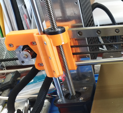
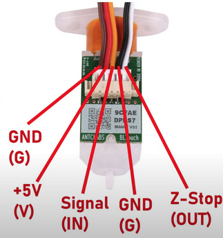
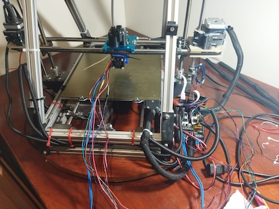
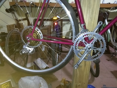
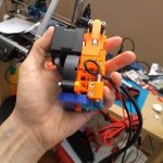
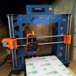
It has been a while since I made a post, so I thought today would be a good day to do so.  I had hoped that there weren’t going to be any more battles with my Mini Rambo install effort on the MendelFlex, but I was wrong.  The next thing that I attempted to accomplish was to get the BLTouch probe working with the Mini Rambo.  Here is a picture of a BLTouch and what the wires are for.

Here is a diagram on how it should be (in theory) attached to the Mini Rambo.

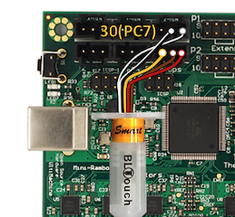
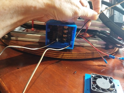
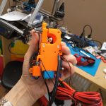
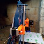
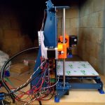
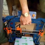
I plugged the BLTouch wires plug into the Mini Rambo Z like shown in the picture above.  I had to switch the brown and red wires in the 3 pin connector because as it was, the wiring in the connector is yellow, red, and brown.  And the connections to the Mini Rambo need yellow, brown, and red.  In the Marlin firmware in the pins_Rambo.h file, I set the servo pin to 30.

#define SERVO0-PIN 30 //BLTouch orange wire

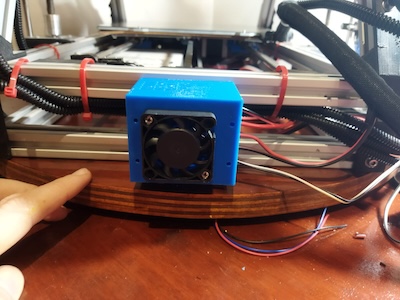
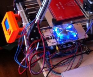
The other wires that I had to check out were the Nozzle/Hotend fan and the print cooling fan.  With the Ramps board I plugged the nozzle/hotend fan into a 12 V connector on the board.  So it ran all the time.  The connectors on Mini Rambo will be controlled by Marlin.

In the Configuration_adv.h file, enable the PROBE_OFFSET_WIZARD to add it to the menu on the printer.

While I was able to get the other components working with the Mini Rambo, I just couldn’t get the BLTouch working with it.  The information available was a bit sketchy.  Plus while trying to extrude some ABS during testing, the nozzle got clogged.  So I just stopped working on the MendelFlex conversion to 24v.

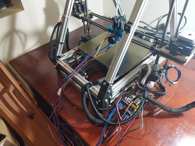
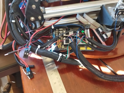
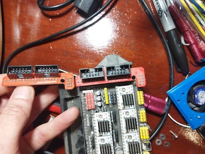
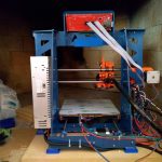
Recently I made up my mind to revert the MendelFlex back to its Ramps 1.4 origins and abandon the 24V effort for a number of reasons.  The Ramps 1.4 12v system worked well enough and the BLTouch probe worked too.  I uninstalled the Mini Rambo and put back the Ramps 1.4 in.  It took me a little bit to make sure the wiring was correct, but I accomplished the task.

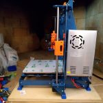
While the X and Y homing are working fine, the Z homing needs some work.  I need to calculate the Z offset again and put it in the settings.  The extruder head just kept going and I had to turn off the printer quickly.  The extruder nozzle did not dig into the print bed because on both of the Z sides there is a floating assembly that stops it from doing that.  The  extruder nozzle just sits on the bed.  The solution to this issue was to switch the connections on the on the Z minimum end stop which is used by the BLTouch probe.  My initial wiring seemed to be correct, but there maybe something in the Marlin firmware that is switching the two pins.  But for now I got it to work and not crash into the bed.

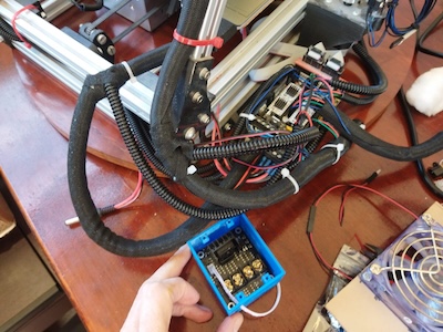
In my prior experimentation with trying to get the external Mosfet to work, one of the things I tried was to turn down the power to the heat bed.  I did this in the firmware.  But I never set it back to full power afterwards.  When I tried to heat up the bed it didn’t work.  The led was just pulsing.  That pulsing should have tipped me off.  I tried another heat bed to see if that was the issue.  The same thing happened, no heat and the led was pulsing.  So the heat bed was probably ok.  At that point I remembered I needed to check the Marlin settings for the power to the heat bed.  After I turned turned the power to full, the heat bed  heated up just fine.

There are a number of good YouTube channels that cover the topic of 3D Printing.  The Teaching Tech YouTube Channel  with Michael has the video that I am following  for the information in this post.  The Teaching Tech website has a lot of good information on 3D Printing.  One of its webpages covers the topic of 3D Printer Calibration.  That particular page has some good information.

There is a wizard for helping set the z offset and it is available in Marlin.  If it has not been set, then it needs to be set in the advanced configuration file (Configuration_adv.h) in Marlin.  The setting is called PROBE_OFFSET_WIZARD and the line defining it should be un-commented to set it.  The other setting that we are interested in is called  PROBE_OFFSET_START.  In most cases it can be left at its default value of -4.  You don’t have to un-comment the line for it unless you want to change the value to something other that -4.  There is another setting in the advanced configuration file that will allow for live Z adjustment.  This could come in handy if our initial adjustment with the probe offset wizard needs some fine tuning in real time.  That setting is called BABYSTEP_ZPROBE_OFFSET.  I will make sure it is set too.

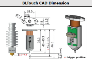
Quick note here.  Since I am using a BL Touch probe, I want to mention that the distance between the retracted probe tip and the hotend tip should be between 2.3mm and 4.3mm.  A distance of  3mm would be good.  Manually lower the hotend tip until it is just touching the bed.  A 3mm allen key is useful to measure the distance from the retracted probe tip to the bed.  Adjust the BL Touch probe if need be.

Once you recompile your Marlin Firmware, the wizard will become available in the Marlin Menu on the printer.  It will be located in Advanced Settings –> Probe Offsets –> Z Probe Wizard.  But before starting the wizard it is recommended to manually heat up the extruder nozzle and bed.  For example with PLA, set the nozzle to something not hot enough to melt the filament.  A setting of 150 will be a good value.  For the bed, we set it to what we  for normally use for PLA and that would be 60.  Once both nozzle and bed heat up to their set temperatures, we will go to the Z Probe Wizard menu.  But first make sure that any filament on the nozzle has been removed.

At the start of using the Z Probe Wizard, the printer will be directed to home the XYZ axis.  Once that has been done, we will be adjusting the Z offset by gradually moving the nozzle closer to the bed.  We will place a piece of paper on the bed and move the nozzle down using fine stepping until it just squeezes the paper between the nozzle and bed.  After that we will have to save our new settings by going to the Store Settings menu.

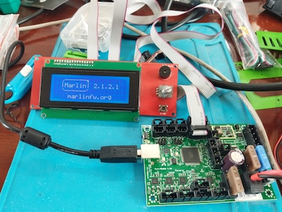
<Maybe A PIcture here fo the menu on the printer>

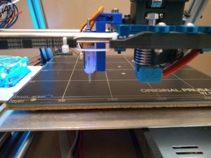
Now we have to test how well we set the Z offset by doing a test print.  From the Teaching Tech web site we will be following the information for setting a good first layer.  I will use the GCode generator from the Teaching Tech website.

===============================================

This is a work in progress.  Going to Publish it so I can read the info while working on the P3Steel settings.

Almost finished.  Will go through the Z Probe Wizard to make sure the directions I wrote down is correct.  Then I will write more about using the GCode generator from the teaching tech website.


Rambo and the MendelFlex

This is a continuation of the effort to use an external mosfet board with the MendelFlex.  I had been able to install Marlin 2.1.2.1 on the Mini Rambo 1.3 while trying a few things that I gathered from my researching on the internet.

Here is a picture of the connections on the Mini Rambo.  A good source for 3D printer information is reprap.org and this is where I got this picture from.  The link of the page is  reprap.org/wiki/Rambo.

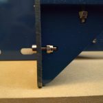
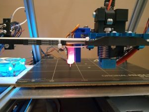
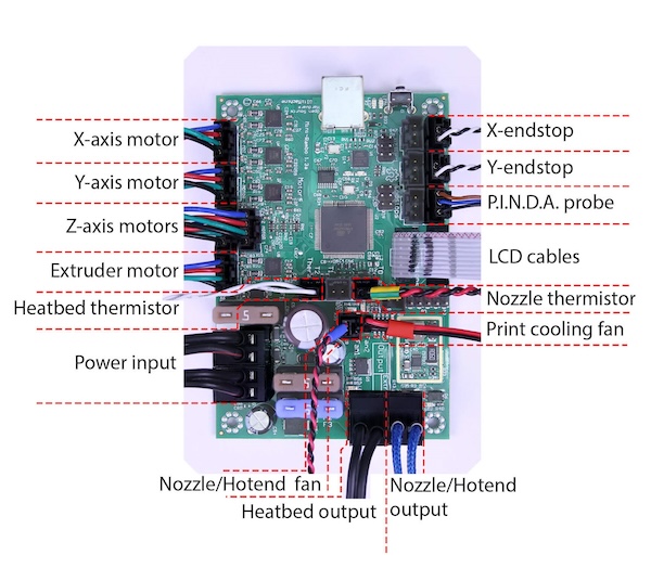
While the picture above show the use of a PINDA probe, the MendelFlex is using a BLTouch probe.  Here is how it should be connected.
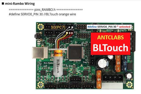
For reference here is a picture of the connections on the Ramps 1.4 controller

Now it’s time to start the swapping out of the controller boards.

After I finished changing the controller, I installed all the wiring while making sure the connections were correct.  I added power to the Mini Rambo and turned it on.  The LCD did not turn on and show the boot up sequence.  I disconnecting all the connectors while leaving the power and the LCD screen connected.  Still nothing happened.  I removed the Mini Rambo and took it over to the test area.  I had an LCD screen there which I had previously used with success on the Mini Rambo.  I plugged in the LCD screen, turned on the power and the LCD showed the boot up sequence.  I went back to the MendelFlex and I connected the Ramps 1.4 board to the LCD screen.  After I connected the power, I turned the MendelFlex on, and the LCD screen displayed the boot up sequence.  As this point I removed the LCD case from the MendelFlex and looked at the LCD board.  After looking at board, I knew what the problem was.  It was a matter of poor quality control.  The connectors were installed backwards.  It had been such a long time that I forgot about the backwards connectors on the LCD setup on the MendelFlex.

The ribbon cable connectors on the LCD adapter card that the Ramps 1.4 used, were backwards as well.  So the two backwards connector sets worked with each other, but not any correctly installed connectors.  In this picture, the adapter board on the left has the connectors installed correctly, while the adapter board on the right does not.

I went ahead and cut some plastic off both of the connectors of the LCD screen so I could plug in the ribbon cables to the correct pins.

After that I turned on the MendelFlex and the LCD finally showed the boot up sequence.

I went ahead and hooked up the wiring. I did a few movement tests.  I moved the X axis, Y axis, and Z axis successfully.  When I continue I will do further testing.

Reworking the MendelFlex

I started testing the MendelFlex again.  I wish I could say it printed fantastic but it didn’t.  I need to do more tuning on it. The bed adhesion was pretty good though.  Since the printer uses 3.00mm filament instead of 1.75mm filament, I have to have 3.00mm filament on hand as well.  The roll of 3.00mm PLA filament that I used before, is really brittle.  It is old and probably needs to spend some time in the filament dehumidifier.  I had some sample translucent red PLA that I pressed into my tests.  The prints that I made were not good.  I opened up a vacuum sealed roll of ABS filament to try out.  Unfortunately I couldn’t get the heated bed temperature to 110°c for the ABS.  When it got around 75°c, the shrill warning beep on the printer went off.  I had to reset the printer.  Using PLA, the heat bed is set to 60°c and the system can handle it. The extra load on the system for temperatures greater than 75°c is too much for the stock Ramps 1.4 controller board.  There are a number of solutions but I am going to try one of the cheaper ones first.  I am going to install an external MOSFET board.  This will take the electrical load off of the controller board.

It did a little bit of rewiring on the system.  I mounted the case for the mosfet board on the printer.

This is what I did for the wiring. I originally had two of the outputs from the PS go to the inputs of the Ramps 1.4 board, one to the 11a side and one to the 5a side. I took the third output from the PS and hooked it up to the external mosfet board on its PS connectors. Correct polarity on all of the outputs. I hooked the heated bed up to the external mosfet board on its heated bed connectors. I hooked up the sensor wires from the external mosfet board to the D8 connector on the Ramps 1.4 board where the heated bed wires were connected.

When the system is powered on there is a red led that lights on the mosfet board. When the Ramps board signals for the heated bed to turn on, a blue led on the mosfet board lights up. The light on the heated bed lights up at the same time showing it is getting power.  The external mosfet got really hot and the the heated bed barely changed temperature.  The alarm sounded on the printer after a short while due to the temperature not rising enough in the set time.  I have a few of those mosfet boards and I tried out another one.  It too didn’t work.  Not sure what’s wrong.

I put a post on the RepRap.org forum thread that was talking about exactly this task which is adding an external mosfet board to the Ramps 1.4 board.

Well on the RepRap.org forum, one senior member said that it looks like my wiring was fine.  There wasn’t any other thing that pointed out what my issue could be.

Maybe I should have shared the PS output that went to the 11A on the Ramps board, with the input on the external mosfet board instead of using that third output.  The output from the PS goes to the external mosfet board and from there to the Ramps board’s 11A inputs.  I tried that alternative wiring and it didn’t work for me either.

Maybe there is something wrong with my Ramps 1.4 board, I don’t know at this point.  I have a Mini Rambo 1.3 controller board that I just installed Marlin 2.1.2.1 on.  It has the settings for MendelFlex.  I can see about swapping the controller boards and testing it out with mosfet board.  Since I am going to probably switch to a 24V setup and this will be good first step in that direction.  My Prusa MK3x has no problem getting the heated bed to 110c using the standard Einsy Rambo 1.2 controller board.  It has a 24V setup.  While I will test the Mini Rambo with the mosfet board, I am not sure I will need to use it when I go to 24V.  But it will be interesting.

The MendelFlex saga continues.


Miyata 310 Completion

I had said that I was going to finish up the Miyata 310 build a few weeks back, but that week turned out to be really hot.  And the next week as well.  So I started working again on the build a few days ago.  I installed the handle bars, the shifters, the brake handles, and started to size the housing for brake cables and shifter cables.

Today I finished cutting the cable housings to size.  Installed the brake and derailleur cables.  Here I am testing the movement of the derailleurs.

Now I am sizing and installing the chain.  I get to use my new Hozan chain tool.  There are three popular ways to size your new chain.  The first method was used by the late Sheldon Brown who was a well known bicycle mechanic and proponent of bicycling.  His website had tons of information on bicycles which I have used on a number of occasions.  His website is still maintained by his friends and family  To use the Sheldon Brown chain sizing method, you put the chain around the larges sprocket on your rear gears and then put the chain around the largest chainwheel on the front. Usually the front derailleur is shifted to the largest chainwheel, but I don’t see that it matters.  Don’t feed the chain through the rear derailleur, just make sure the derailleur is out of your way by shifting it to the smallest sprocket.  But make sure the chain fits on every tooth of the rear large sprocket that it can be on.  As the chain is around the rear large sprocket and the front largest chainwheel, pull the chain tight and find the closest matching link that you can connect to.  Then go back down the chain one link (maybe 2 if you are using a master link)  and at that point is where you will break the chain to size it.

The second chain sizing method needs the bicycle to be on flat and level ground.  You will feed the chain (which has the end that with accept the pin) around the smallest chainwheel on the front.  Next feed the other end of the chain around the smallest sprocket on the rear and also around and through the rear derailleur pickup wheels.  The chain end from the front will overlap the rear end of the chain.  Pull the chain ends gently together until the point where the cage of the rear derailleur moves forward.  At this point the chain coming off the rear derailleur ideally should have enough clearance not to rub against the top guide pulley on the derailleur.  Basically there should be a minimum of 1/2″ or 15mm gap.  On the overlap, you will break the chain at the point where the proper ends meet.  Note that if you are using a power link, then you have to go one link farther.

The third chain sizing method uses mathematics to calculate the chain length.  First you need to find out how many teeth your biggest sprocket on the rear  has and then find out how many teeth your biggest chainwheel on the front has.  Then measure the length of your chain stay which will be from the center of your rear wheel to the center of your chainset.  Measure it to the closest .125″ (1/8″).   I am going to do a calculation using the numbers I gathered from my Miyata which has a 53 tooth front chainring, a 34 tooth large rear sprocket, and a length of 16.25″ for the chainstay.  So the equation will be this for the Miyata:

(16.25 x 2) + (53 / 4) + (34 / 4) + 1

32.5 + 13.25 + 8.5 + 1 = 55.25″

This last method is especially helpful if you change you rear sprocket/cassette or your front chainwheel.  I was familiar with the first two methods, but not this third method.  I used the second method when I sized up the new chain for my Fuji build.  This time I am going to use the Sheldon Brown sizing method.  After I size the chain, I will compare the length that I come up with to the Math sizing method and see how close they are.

In the picture I made a mistake marking the link, I need to go over to the start of the next link.  So instead of 55″ it was almost 55.5″.  So 55″ and 55.5″ were still in the ballpark and very close to the measurement of 55.25″ that I calculated.

I was able to install the chain but had a little bit of trouble with the pin for the Shimano chain.  You are supposed to install a chain with the side that has writing on it facing the outside.  But this Shimano chain had writing on both sides, so I am not sure which side is suppose to face out in this case.

After I installed the chain I adjusted the high/low setting for the derailleurs.  Then I took the Miyata on a few test rides.  I moved the saddle back twice, a little bit after each of two short rides in the neighborhood.

I completed about 99% of the build.  I need to install the toe clips and a speedometer I got for it.  But I will mark the build as completed!


Hozan Bicycle Tools

I don’t remember when I first became aware of Hozan Tools, but they have been around since 1946.  Besides making bicycle tools, they make tools for the electronics industry.

I have a number of their tools on my wish list.  The first one is the C-702 Spoke Threading Machine.  It is for use with round spokes.  There are 3 different cutting head sizes available (13, 14, and 15) depending on your spoke thickness.  You can cut a long spoke to the size you need and then use the C-702 to put threads on the spoke by turning the crank arm to do so.   It actually cold rolls the tread on to a spoke.  It comes in handy for those people who build a lot of bicycle wheels.  I have yet to build my first wheel, but that is one of the things I want to do.  You can get it on Amazon with one cutting head for around $119 USD which is cheaper than I have seen it on eBay.  Also on Amazon I have seen a cutting head is around $72 USD which is the cheapest I have found.

I saw a Hozan C-701 Spoke Threading Machine on eBay a while back.  It is motor driven.  I only saw that one unit there and someone snatched it up.  I saw a few videos of it in action and it was very easy to use.  It was around $450 USD on eBay which is a lot more expensive that you can get a C-702 on Amazon.  But I saw that a brand new unit with a #13 head at Modern Bike was $1500 USD but with free shipping!

The Hozan C-701 is not the most expensive Spoke Threading Machine I’ve seen online.  Wheel Fanatyk has a Morizumi that will cut and thread the spoke like you can get from the factory.  But it comes in at a whopping $3800 USD!  It is manual action where you pull a lever down and cut the spoke.  You then put the spoke into the threading area where you pull a lever down and push it back up for a finished spoke.  Really fast if you are producing a lot of spokes.  Not sure how many spokes you need to run through the machine before you get a return for your money.


Actually I forgot about the Phil Wood spoke machine which is an astronomical $7050 USD!  Not even going to show a picture for that thing.  I wonder how much the Phil Wood name adds to the price.

I got off the subject of the post, namely Hozan tools.  I have a number of cheap bicycle chain tools.  I have one that is part of a BikeHand tool set, and a few others that I picked up from various places.  All of them work but they are basically junk.  Which brings me to my latest chain tool, the Hozan C-371.

The C-371 is a heavy duty chain tool it dwarfs the other chain tools.  It is prescision made.  And at $74 USD it better be.

The BikeHand chain tool broke while I was using it a while back.  The metal piece that the chain fit over broke right off.  The metal isn’t very strong.


The handle of the C-371 holds a spare chain link press pin.

I am going to be using this tool when I install the chain on my Miyata 310 this week.


Miayta 310 Build Progress

Recently I spent some time working on the Miyata 310.  I was going to use a 7 speed IRD freewheel sprocket but unfortunately there was some binding between it and the frame.  So I had to use the gold 5 speed New Old Stock (NOS) Suntour freewheel that I had.  It looks good on the rear wheel.  I also added a Suntour chain guard that I picked up.  A lot of people remove them, but I added it for a retro look.

I got a Miyata crankset (made by Sakae) from ebay a while ago and I was going to install it on the bicycle.  But unfortunately when I tried to install it, there was some binding on the frame as well.  Because the mounting bolts for the small chainwheel are too far in, they scrape on the frame as the crank turns.  So I can’t use it.  It does look nice.  I guess I will create a shadow box for those parts that I can’t use.

So I am going to go with the Sugino Mighty crankset that I already had on the frame.  It is a nice crankset.  I believe I mentioned before that Sugino still manufactures cranksets in Japan.  Good quality parts.

Today I did a few things on the build.  I added gear cable guides, cut the stem of the fork to size, put in the seat post, put in the handle bar stem, and put on the derailleurs (both Suntour NOS).  I am using the handle bar stem that I previously had on my Fuji Team.  The seat post is a suspension post that I got in 26.6mm width to fit in the seat tube.  I got a tool from Stein Tool in the US for cutting the 1″ threaded fork tube to size.  Worked great. Used a file on the burs at the end of the cut.


This coming week I will go ahead and finish it up.

Fuji Team Issue Build

At the same time that I got the Miyata 210 frame, I purchased a Fuji Team Issue frame with a front fork.  The frame and fork were carbon fiber and had been listed as being repaired.  Since the seller was a bike shop with a very good rating, I crossed my fingers and hoped it would be ok.  From the pictures nothing seemed to be wrong with it.  And when I received it, everything was fine.  This is the frame that I intend to use as the basis for a bike that I would ride in the neighborhood with my family.  Here is a picture of the frame from the eBay listing and a picture of a complete 2008 model.

This build is a nod to the Fuji Finest that I liked back in the 70s.  This build turned out pretty well.

While I still intend on adding the toe clips and straps that I have on hand, the build is pretty much completed.  I didn’t do a build using original components.  I mixed and matched components that I thought would work well.  One component that I didn’t go with, was standard drop handlebars.  This was due to the negative effect that bending down while gripping them would have on my lower back.  So I opted to use Wald 870 high rise handlebars which would allow me to sit fairly upright.  I paired up some Dia-Compe DC188 brake levers (with matching handle grips) along side the Wald 870 handlebar.  Topping that off that setup with an IRD Power Ratchet Thumb Shifter set.  I included a number of Campagnolo components in the build.  The front and rear brakes are Campagnolo Centaur Dual Pivot Caliper brakes.  The front and rear derailleurs are Campagnolo Racing T derailleurs.  Both of the wheels were built using Campagnolo hubs with Mavic CXP Pro 15mm rims.  The tires are 700-28c Panarace Gravel Kings.  I used Velo Orange Cable sets for the brakes and derailleurs.  The saddle is a Fuji Velo which is on a generic compression seat tube.  The seat tube along with a 90mm Cirrus Cycles Suspension Stem dampens the bumps a bit.  The bottom bracket is an IRD QB-55 (127.5mm x 68mm) with English Threads.  The crankset is a triple from a Fuji S10S (most likely from the 80s).  I used a pair of MKS Sylvan Touring (Black and Silver) pedals.  To finish off the bike I used a kickstand that attached to the bike using the quick release on the rear wheel.  The frame, saddle, and crankset all say Fuji on them.

I will be exclusively riding around the roads in my neighborhood.  I don’t intended to ride the bike on the open roads.  It is too bad the roads in my neighborhood aren’t paved, but it is what it is.

P3Steel Build

Over a period of time from July 2018 to February 2019, I put together a 3d printer.  It is a P3Steel design that mostly comes from Thingiverse thing 157303 by irobri.  This design was based on the work by twelvepros.  If you are interested in the designers, then you can look them up at Thingiverse.  I made a few tweaks to the design using DraftSight, which is a 2D CAD Drafting and 3D Design Software program by Dassault Systems.  I incorporated the lcd holder from another variant into my build.  This is basically a version 2.0 of the P3Steel.

The frame is made of 3mm steel and was laser cut by a local company.  The other parts that I used for the build came from various places.  These places include Prusa Research, Banggood, E3D, and GeckoTek.  The bolts that hold the frame together came from Albany County Fasteners’ online store.  There were also a few printed parts (like the feet and carry handle) that came from other Thingiverse designers.  The orange printed parts came from Prusa Research.

I put it together for a friend who will need to fine tune it.  I got everything working mechanically, but they will have to do all of the final adjustments for printing.  I helped jumpstart his 3d printing effort.

Here are photos that I took over that time period.

Changing to the BLTouch

Unfortunately the Pinda Probe experiment did not work out as I had hoped it would.  The MK42 bed was really made to be used with the Prusa Pinda Probe  in a MK2s.  Meaning the offsets from the hotend and the Pinda Probe needed to match what Prusa is using.  That is because the MK42 has nine probe points that the Pinda Probe will detect correctly when it is over them.  Other areas on the MK42 bed don’t trigger the probe.

So I removed the Pinda Probe and installed a BLTouch probe.  This is the new Smart version of the BLTouch.  It took me a while to install it.  I used an adjustable mount for a BLTouch that I got from Thingiverse.com.  The mount was for a different printer, but I was able to use it with a little tweaking of the mounting holes.  I used one of Thingiverse’s printer services (Treatstock) to have the mount printed for me.  I would have liked to have had the BLTouch mounted closer to the hotend, but due to the design of the carriage I was not able to.  It is about 52mm away from the hotend now.  The minimal distance is 15mm.  The mount was for made for another printer after all.  Maybe in the future I can do something about that and get it a bit closer.  Probable will have to design a new mount.

I made more changes to the Configuration.h file for my Marlin setup.  Since I was already familiar with what I had to do, it didn’t take terribly long.  I was able to set up the bed leveling using the BLTouch.  The printer probes the bed with the BLTouch.  Next step will be to try to print something.


I did make another minor change to the printer.  I changed the LCD mount.  This mount blends in more than the other one did.  Note that the picture with the first lcd mount was taken before I made a lot of the prior changes.