MendelFlex renewal

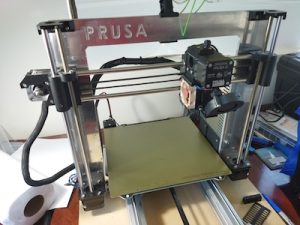
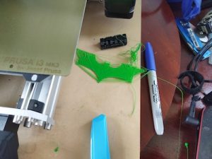
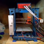
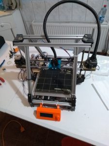
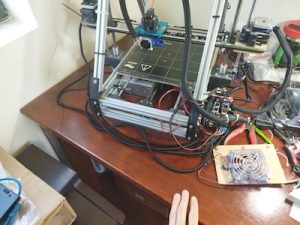
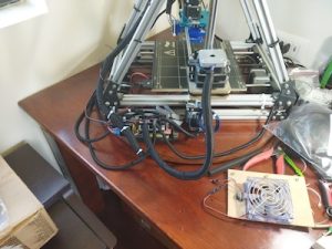
After I finished with the build of my Prusa MK3x, I turned my attention towards my original 3D printer, the MendelFlex.  I needed to get it back to a working state and also improve its printing ability.  The first thing on the list was to fix the wiring.  It was a mess literally.

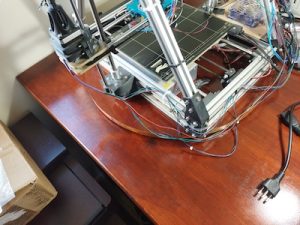
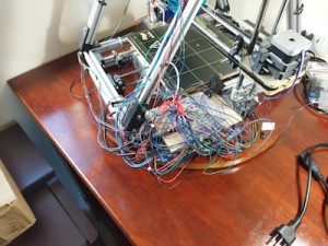
Plus I needed to repair the wires to the cooling fan on the printer because one of our cats decided to bite it in half.  They have a bad habit of doing the same thing to wires on earbuds, on USB cables, on ethernet cables, and other things.  We have had to put some plastic conduit around the cables to protect them.  I am going to be doing the same thing while I clean up the wiring.

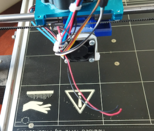
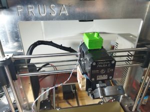
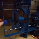
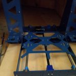
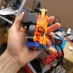
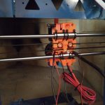
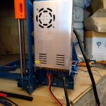
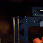
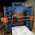
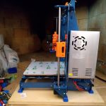
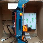
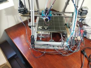
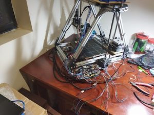
Initially the ramps controller board on the printer was in a  different location.   It was in the area under the heatbed where the power supply is.  It made it hard to easily access the wiring on the ramps controller board.  So I moved it to the side of the printer.  I also fashioned a better cooling solution by putting a large fan over the ramps board.  The fan was something that I pulled from a power supply.  The fan has led lights that turn on when powered up.  Also the printer initially had a printed extruder carriage, but I replaced it with a metal carriage.  I replaced the bed assembly and heatbed with a bed assembly I had for a P3 Steel printer along with a Prusa Mk42 heatbed.  I added in a BLTouch sensor while doing all of that.  In the process of rewiring the printer I shortened a number of the wire leads.  One reason I kept them long was because I didn’t have crimpers for the connectors needed.

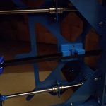
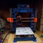
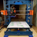
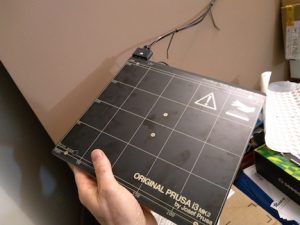
While working on the wiring I also replaced the Prusa MK42 heatbed with a Prusa MK52 heatbet with the removable metal plate.  The removable plate works great on my Prusa MK3x with good adhesion!

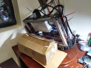
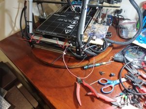
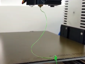
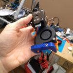
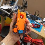
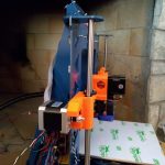
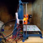
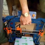
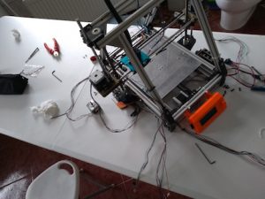
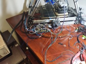
The last thing I did was to add a blower fan for print cooling.  I had to fashion a mount for it using parts that I had and a bit of hot glue.  By the way it did work after I finished all the wiring.  Using Pronterface I was able to send a M106 s127 command to the printer to turn it on and set the speed to 50%.  And then an M107 command to stop it.  I made extensive use of zip ties to keep the wiring harnesses in place and out of the way.
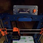
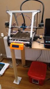
Wiring completed!

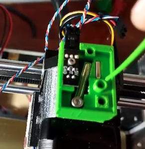
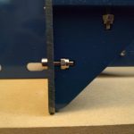
I did run into one small issue when I was testing out the electronics on the printer.  I was able to engage and move the X, Y, and Z motors from Pronterface.  But when I tried to home the printer, the Y motor didn’t respond for some reason. The X and Z were fine.  After close inspection I found out the the arm on the Y switch stuck into the closed position so the printer thought that Y was where it should be.  After fixing that, the printer was able to home just fine.

The next thing I will be doing is to update Marlin.  Currently I am running 1.1.6.  I will do some research and figure out which version will be best to upgrade to.

Until next time, Happy Printing!

Finally finished building my Prusa MK3x

This build wasn’t a straight up kit so I ran into issues. Here are some of those issues that occurred after building my Prusa MK3x.  From Prusa I had gotten all the steppers, the sensors, and various other parts.  The frame pieces I got from Aliexpress.  The controler board I got from Ultimaker, but it is the one that Prusa also uses. So this is sort of a Frankenstein build.  This build has been in the making for quite a few years.  I should have just gotten a complete kit from Prusa and built that.

Over the years Prusa has upgraded its MK3 printer line with the latest iteration being the MK3S+.  After I finished the build I plugged it in and tried out the calibrations.  While the stepper motors were functioning correctly, things weren’t working.  The filament sensor didn’t seem to work.  The wiring was correct, but it didn’t know if the filament was loaded or not.  The printer kept going through its bed leveling routine before doing a print.  So I had to turn off the filament sensor to continue.  Another issue was that the extruder was not working.  The stepper motor was turning, but no filament was extruding.  The firmware does make you heat up the bed and the hotend before you attempt to do so.  It seemed that filament didn’t go all the way to the hot end for some reason.  So I took apart the hot end and I saw that the PTFE tube in the heatsink was deformed at the opening.  I had another piece so I replaced it.

I reinstalled all the pieces and tried again.  While I was able to insert the filament a little bit more, I still couldn’t extrude any filament.  So I took apart the hotend again.  I looked into the hotend and there was a little bit of plastic blocking the inside of the tube.  The plastic bit had broken off of the retainer clip for the PTFE tube that fit into the heat sink.  Not sure how that happened, but I replaced it.

After I reassembled the extruder, I tried again to extrude some filament and I was successful!

But I needed to check the tension on the gears in the extruder.  There might be too much tension.  I checked the tension on the belts and adjusted them to be with in the stated tolerances.  I used the online app that Prusa had on their website to test the harmonics of the belts after you pluck them.  It seems to work after a fashion.

I did a few test prints and I see that I still need to do some more adjustments to my prints up to par.   One thing is that the bed surface probably should have been cleaned, but I just wanted to see if I could even print.  Remember I said that the filament sensor didn’t see to work, I had to turn off the filament sensor in the settings to even get a print to start.  Part of the printing process the printer does a bed leveling check and goes over like 9 different points on the heatbed taking measurements.  Well after it did the check, it wanted me to unload the filament and then load it back in again.  It went to do the test again.  And after it finished the second time, it again wanted the filament to be unloaded/loaded.  I did that again for a third time before I thought I would turn off the filament sensor in the settings.  After that I was able to start printing.  They weren’t very good prints but it was trying.  But it is a work in progress!  Need to make more adjustments.

My z offset set  apparently is still too high.  So I need to lower it.  After trying a few different Z offsets, I was able to set the Z offset to -0.850mm and get a good first layer.  After that I was able to get a nice print of the Batman logo.

The feeding of the filament just didn’t seem correct also.  I believed that this was throwing things off.  Since the extruder setup I have on the printer is a MK3/MK2.5 type, there were two allen screws that needed to be adjusted.  Looking at the prusa site, it said that the top of the allen screw heads should be flush with the hole the went in.  Previously I had each around 8 full turns in.  I made it flush like the Prusa guide noted.  Then I started over with the first layer test.

I decided to use an IR filament sensor instead of older type I initially installed.  So one last thing I did was to print out a Bondtech IR filament sensor housing adapter that I found online.  Due to the parts I have, the older non IR filament sensor fits my extruder housing, but not the newer IR filament sensor.  While the print turned out great, I had to order a newer IR filament sensor since the rev I had was 1.1 and only rev 1.4 or above works with the firmware.


Until next time.  Happy Printing!

P3Steel Build

Over a period of time from July 2018 to February 2019, I put together a 3d printer.  It is a P3Steel design that mostly comes from Thingiverse thing 157303 by irobri.  This design was based on the work by twelvepros.  If you are interested in the designers, then you can look them up at Thingiverse.  I made a few tweaks to the design using DraftSight, which is a 2D CAD Drafting and 3D Design Software program by Dassault Systems.  I incorporated the lcd holder from another variant into my build.  This is basically a version 2.0 of the P3Steel.

The frame is made of 3mm steel and was laser cut by a local company.  The other parts that I used for the build came from various places.  These places include Prusa Research, Banggood, E3D, and GeckoTek.  The bolts that hold the frame together came from Albany County Fasteners’ online store.  There were also a few printed parts (like the feet and carry handle) that came from other Thingiverse designers.  The orange printed parts came from Prusa Research.

I put it together for a friend who will need to fine tune it.  I got everything working mechanically, but they will have to do all of the final adjustments for printing.  I helped jumpstart his 3d printing effort.

Here are photos that I took over that time period.

3D Printer revamp

It has been a while since my last post. I hadn’t worked on anything in a while.  I am continuing with my quest to get my 3D printer to print correctly.  I had been trying to get the printer to print without having the filament ball up on the nozzle.

I ordered a new extruder assembly from the MendelFlex guy, but not sure when he will finish the batch he is working on.  It has been a while.  Any day now.

The OVM20 board has had some issues with the micro usb connector.  It kept disconnecting.  Very hard to upload an updated sketch when it keeps disconnecting.

I tried to use an avr programmer I had to program the OVM20, but it failed on the verify of the write to the on board flash. So I removed the OVM20 and went back to a two board setup using a Mega2560 and a Ramps 1.4.  I am using the Ramps 1.4 board that I got from the maker of the OVM20 board.  His boards are well made, inspite of the usb connector issue I am having. On his next go around with the design of the OVM20, I suggested that the board not use a micro usb connector but a usb b connector like the mega uses and other boards use. Those connectors don’t allow the cable to wobble when plugged into it.

After I reinstalled the boards, I had to adjust the step settings for the three axises and the extruder.  They were off now because the OVM20’s settings for stepping is hard set to 32 steps while the Ramps 1.4 I have it set to 16 steps.  Once the movement on the axises was set, I adjusted the settings for the extruder. I heated the hot end up to 185 C and then extruded 100mm of filament.  The amount extruded was off so I had to adjust it and try again.  I had it set correctly after two tries.

The plate glass did not sit completely flat in its 4 corner brackets. On two corners they lifted up a bit. I believe that this was affecting the print adhesion, but probably not the only thing.  I got 4 large binder clips and used them to hold the glass in place. I also got a simple bed leveling sensor to help with things.

I changed the marlin firmware to add in bed leveling in the menu options.  I couldn’t get the simple bed leveling sensor to work out. The bed isn’t level. I put the binder clips in place, but they did not seem to help.  I going to change out the print bed. I have a 4mm thick aluminum plate that I can use. It was made to match up with the MK2b size heaters. I will put a PEI sheet on top of the aluminum plate and print on that.

After thinking about it for a while, I won’t be using the aluminum plate and MK2b combo.  I have a genuine MK42 heatbed from Prusa Research that I will use.  It also works with a Pinda probe which I have. The MK42 is an aluminum plate with a built in heater.  It also has a PEI sheet on top. One bad thing is that I need to rearrange the electronics since the power cable for the MK42 won’t reach where the electronics are currently located.

I had some cork backing that I put on the bottom of the MK42 for added insulation.  I will have to mount the Pinda probe later after I figure how I am going to attach it.

Before I mount the MK42, I have to move the electronics. I swapped the two z motors also because the wiring on one motor was cut short before to reach the electronics near it.

Because of the heatbed’s power cable, the power supply would have to be moved also.  I removed the PS along with the Mega2560/Ramps setup.  I then installed the new MK42.


I moved the PS and the electronics into their new positions.

Lastly I hooked up all the wiring for the stepper motors, the end stops, the heatbed, the hot end, the thermistors, and then the fans.

Back on the testing center table ready to see how things go.

That’s all for now folks!